JF2BM TRANSFER / 4WD / AWD TRANSFER ASSEMBLY INSTALLATION
CAUTION / NOTICE / HINT
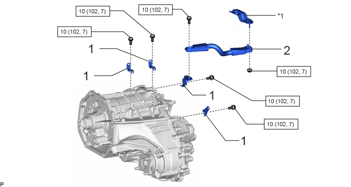
| Procedure | Part Name Code |

|

|

|
|
|---|---|---|---|---|---|
| 1 | INSTALL WIRE HARNESS CLAMP BRACKET | - | - | - | - |
| 2 | NO. 2 GROUND WIRE | 82286A | - | - | - |
| *1 | WIRE HARNESS CLAMP BRACKET | - | - |

|
N*m (kgf*cm, ft.*lbf): Specified torque | - | - |
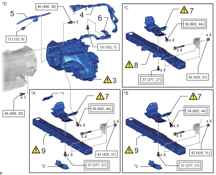
| Procedure | Part Name Code |
|
|
|
|
|---|---|---|---|---|---|
| 3 | TRANSFER ASSEMBLY | 36100 | ( ) |
- | - |
| 4 | WIRE HARNESS AND TRANSFER BREATHER HOSE SUB-ASSEMBLY | - | - | - | - |
| 5 | TRANSMISSION CONTROL CABLE ASSEMBLY | 33820B | - | - | - |
| 6 | CONNECT WIRE HARNESS CLAMP BRACKET | - | - | - | - |
| 7 | REAR ENGINE MOUNTING INSULATOR | 12371A | () |
- | - |
| 8 | NO. 3 FRAME CROSSMEMBER ASSEMBLY | - | () |
- | - |
| 9 | NO. 3 FRAME CROSSMEMBER ASSEMBLY | - | () |
- | - |
| *A | for V35A-FTS | *B | for F33A-FTV |
| *C | for 1GR-FE | *D | w/o Urea SCR System |
| *1 | REAR ENGINE MOUNTING HEAT INSULATOR | *2 | NO. 3 ENGINE MOUNTING HOLE COVER |

|
Tightening torque for "Major areas involving basic vehicle performance such as moving/turning/stopping": N*m (kgf*cm, ft.*lbf) |
|
N*m (kgf*cm, ft.*lbf): Specified torque |
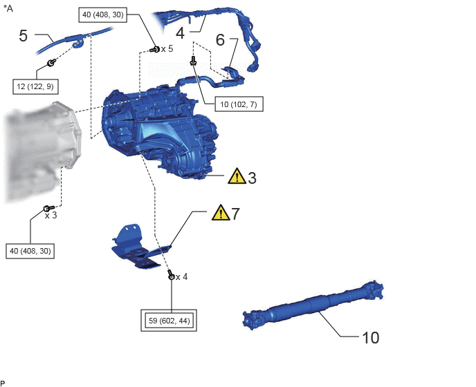
| Procedure | Part Name Code |
|
|
|
|
|---|---|---|---|---|---|
| 3 | TRANSFER ASSEMBLY | 36100 | () |
- | - |
| 4 | WIRE HARNESS AND TRANSFER BREATHER HOSE SUB-ASSEMBLY | - | - | - | - |
| 5 | TRANSMISSION CONTROL CABLE ASSEMBLY | 33820B | - | - | - |
| 6 | CONNECT WIRE HARNESS CLAMP BRACKET | - | - | - | - |
| 7 | REAR ENGINE MOUNTING INSULATOR | 12371A | () |
- | - |
| 10 | FRONT PROPELLER SHAFT ASSEMBLY | 37140 | - | - | - |
| *A | w/ Urea SCR System | - | - |
|
|
Tightening torque for "Major areas involving basic vehicle performance such as moving/turning/stopping": N*m (kgf*cm, ft.*lbf) |
|
N*m (kgf*cm, ft.*lbf): Specified torque |
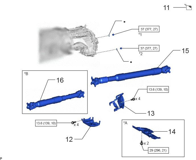
| Procedure | Part Name Code |
|
|
|
|
|---|---|---|---|---|---|
| 11 | ADD TRANSFER OIL | - | - | () |
- |
| 12 | LOWER TRANSFER CASE PROTECTOR | 36179 | - | - | - |
| 13 | TRANSFER HEAT INSULATOR | 36336 | - | - | - |
| 14 | TRANSMISSION UNDER COVER ASSEMBLY | 51470 | - | - | - |
| 15 | REAR PROPELLER SHAFT ASSEMBLY | 37110F | - | - | - |
| 16 | FRONT PROPELLER SHAFT ASSEMBLY | 37140 | - | - | - |
| *A | w/ Cover | *B | w/o Urea SCR System |
| *1 | FILLER PLUG | *2 | DRAIN PLUG |
|
|
N*m (kgf*cm, ft.*lbf): Specified torque | ● | Non-reusable part |
PROCEDURE

 1.INSTALL WIRE HARNESS CLAMP BRACKET
- Torque:
- 10 N*m (102 kgf*cm, 7 ft.*lbf)
82286A 2.INSTALL NO. 2 GROUND WIRE
- Torque:
- 10 N*m (102 kgf*cm, 7 ft.*lbf)
36100 3.INSTALL TRANSFER ASSEMBLY
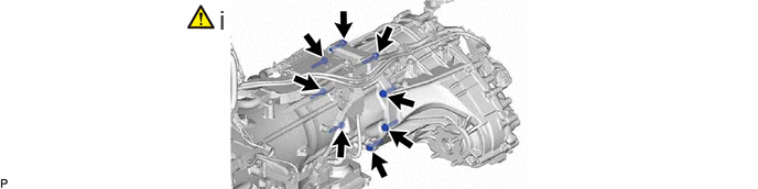
Install the transfer assembly to the automatic transmission assembly with the 8 bolts.
- Torque:
- 40 N*m (408 kgf*cm, 30 ft.*lbf)
- NOTICE:
-
When installing the transfer assembly to the automatic transmission assembly, make sure that the automatic transmission assembly and oil seal do not become damaged.
4.CONNECT WIRE HARNESS AND TRANSFER BREATHER HOSE SUB-ASSEMBLY
33820B 5.CONNECT TRANSMISSION CONTROL CABLE ASSEMBLY
- Torque:
- 12 N*m (122 kgf*cm, 9 ft.*lbf)
6.CONNECT WIRE HARNESS CLAMP BRACKET
- Torque:
- 10 N*m (102 kgf*cm, 7 ft.*lbf)
12371A 7.INSTALL REAR ENGINE MOUNTING INSULATOR
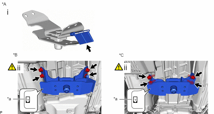
| *A | for V35A-FTS | *B | for V35A-FTS, F33A-FTV |
| *C | for 1GR-FE | - | - |
| *a | Front Mark | - | - |
for V35A-FTS:
Install the rear engine mounting heat insulator to the rear engine mounting insulator as shown in the illustration.
Make sure that the front mark is facing in the correct direction, and then install the rear engine mounting insulator to the transfer assembly with the 4 bolts.
- Torque:
- 59 N*m (602 kgf*cm, 44 ft.*lbf)
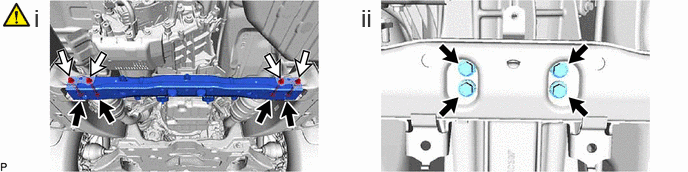
8.INSTALL NO. 3 FRAME CROSSMEMBER ASSEMBLY (for 1GR-FE)

|
Bolt |

|
Nut |
Install the No. 3 frame crossmember assembly with the 4 nuts and 4 bolts.
- Torque:
- 42 N*m (428 kgf*cm, 31 ft.*lbf)
- NOTICE:
-
Make sure to install the nuts so that they are facing the rear of the vehicle.
- HINT:
-
Hold the bolts to tighten the nuts.
Connect the rear engine mounting insulator to the No. 3 frame crossmember assembly with the 4 bolts.
- Torque:
- 37 N*m (377 kgf*cm, 27 ft.*lbf)
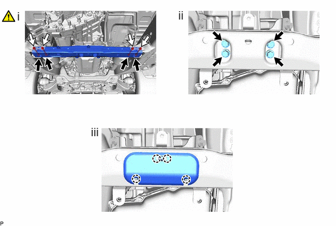
9.INSTALL NO. 3 FRAME CROSSMEMBER ASSEMBLY (for V35A-FTS, F33A-FTV (w/o Urea SCR System))
|
|
Bolt |
|
Nut |
Install the No. 3 frame crossmember assembly with the 4 nuts and 4 bolts.
- Torque:
- 42 N*m (428 kgf*cm, 31 ft.*lbf)
- NOTICE:
-
Make sure to install the nuts so that they are facing the rear of the vehicle.
- HINT:
-
Hold the bolts to tighten the nuts.
Connect the rear engine mounting insulator to the No. 3 frame crossmember assembly with the 4 bolts.
- Torque:
- 37 N*m (377 kgf*cm, 27 ft.*lbf)
Attach the claw and install the No. 3 engine mounting hole cover to the No. 3 frame crossmember assembly.
37140 10.INSTALL FRONT PROPELLER SHAFT ASSEMBLY (w/ Urea SCR System)
11.ADD TRANSFER OIL
|
|
Click here() |
36179 12.INSTALL LOWER TRANSFER CASE PROTECTOR
36336 13.INSTALL TRANSFER HEAT INSULATOR
- Torque:
- 13.6 N*m (139 kgf*cm, 10 ft.*lbf)
51470 14.INSTALL TRANSMISSION UNDER COVER ASSEMBLY (w/ Cover)
37110F 15.INSTALL REAR PROPELLER SHAFT ASSEMBLY
37140 16.INSTALL FRONT PROPELLER SHAFT ASSEMBLY (w/o Urea SCR System)