Home › Drivetrain › DRIVE SHAFT / PROPELLER SHAFT › FRONT PROPELLER SHAFT ASSEMBLY › from 2021.07
RM38G0E _52 Drivetrain _101647 DRIVE SHAFT / PROPELLER SHAFT _0470832 FRONT PROPELLER SHAFT ASSEMBLY A

DRIVE SHAFT / PROPELLER SHAFT  FRONT PROPELLER SHAFT ASSEMBLY  INSTALLATION  


CAUTION / NOTICE / HINT
COMPONENTS (INSTALLATION)
C463221N02
2.125,0.406 2.927,0.615 0.802,0.208 2.063,0.344 3,0.677 0.938,0.333 5.49,4.781 6.292,5.021 0.802,0.24 5.656,0.448 6.635,0.781 0.979,0.333 4.948,0.406 7.073,1.771 2.125,1.365 1.875,2.854 7.083,5.667 5.208,2.813 2.073,5.146 3,5.5 0.927,0.354 2.135,5.219 2.938,5.438 0.802,0.219 5.719,0.521 6.573,0.719 0.854,0.198 6.177,3.333 6.948,3.573 0.771,0.24 3.583,0.135 4.385,0.344 0.802,0.208 3.521,0.073 4.458,0.406 0.938,0.333 5.656,3.542 5.656,3.833 5.656,3.833 5.948,3.833 true 5.771,1.448 6.021,1.448 true 2.156,2.302 1.927,2.302 1.927,2.302 1.927,1.74 true 3.573,0.229 3.344,0.229 3.344,0.229 3.344,0.615 true 2.115,0.51 1.885,0.51 1.885,0.51 1.885,0.948 true 5.708,0.635 5.479,0.635 5.479,0.635 5.479,1.073 true 6.427,0.229 6.844,0.229 true 5.063,4.896 5.479,4.896 true 2.948,5.333 3.365,5.333 true 6.229,3.042 5.948,3.458 5.948,3.458 6.177,3.458 true 4.094,3.302 3.865,3.302 3.865,3.302 3.865,3.74 true 2.792,4.823 3.208,4.823 true 3.25,0.75 3.563,0.948 0.313,0.198 10 false x 4 3.521,0.698 3.833,0.896 0.313,0.198 10 false x 4 1.708,1.104 2.083,1.313 0.375,0.208 10 false x 4 1.979,0.948 2.365,1.156 0.385,0.208 10 false x 4 5.573,1.01 5.938,1.219 0.365,0.208 10 false x 2 3.417,5.385 3.844,5.615 0.427,0.229 10 false x 4 5.063,4.948 5.49,5.177 0.427,0.229 10 false x 4 3.458,4.521 3.833,4.719 0.375,0.198 10 false x 4 6.344,2.906 6.698,3.104 0.354,0.198 10 false x 4 2.167,0.448 3,0.625 0.833,0.177 8 false 88.3 (900, 65) 5.792,0.542 6.708,0.729 0.917,0.188 8 false 15.7 (160, 12) 5.01,0.469 5.385,0.698 0.375,0.229 10 false *B 1.917,2.906 2.292,3.135 0.375,0.229 10 false *A 5.563,4.833 6.313,5.021 0.75,0.188 8 false 42 (428, 31) 2.219,5.271 2.99,5.458 0.771,0.188 8 false 37 (377, 27) 6.208,3.385 7,3.604 0.792,0.219 8 false 13.6 (139, 10) 2.542,2.177 2.823,2.531 0.281,0.354 18 false 1 6.438,1.26 6.719,1.615 0.281,0.354 18 false 2 6.135,0.052 6.417,0.406 0.281,0.354 18 false 3 4.146,3.135 4.427,3.49 0.281,0.354 18 false 4 6.031,3.667 6.313,4.021 0.281,0.354 18 false 5 2.552,4.729 2.823,4.927 0.271,0.198 10 false *1 3.646,0.167 4.479,0.344 0.833,0.177 8 false 88.3 (900, 65)

Procedure Part Name Code
Z101186

Z101188

Z101187

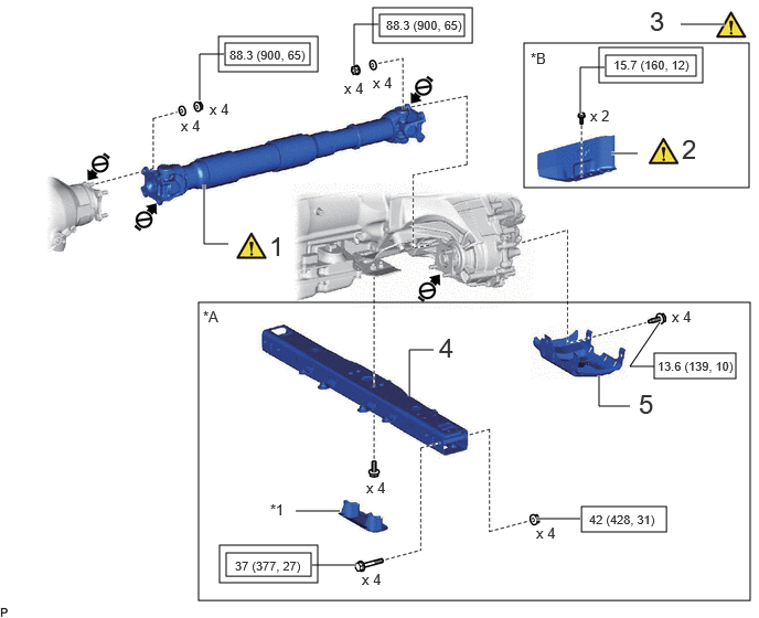
1 FRONT PROPELLER SHAFT ASSEMBLY 37140 (Click here) - -
2 NO. 2 PROPELLER SHAFT HEAT INSULATOR - (Click here) - -
3 SEPARATE UREA TANK SUB-ASSEMBLY 77801 (Click here) - -
4 NO. 3 FRAME CROSSMEMBER ASSEMBLY - (Click here) - -
5 TRANSFER CASE LOWER PROTECTOR 36179 - - -

*A w/ Urea SCR System *B w/o Urea SCR System
*1 NO. 3 ENGINE MOUNTING HOLE COVER - -
V111893

Tightening torque for "Major areas involving basic vehicle performance such as moving/turning/stopping": N*m (kgf*cm, ft.*lbf)
V100146

N*m (kgf*cm, ft.*lbf): Specified torque
V103638

Do not apply lubricants - -

C463206N05
2.979,5.448 3.823,5.667 0.844,0.219 2.094,3.865 2.938,4.083 0.844,0.219 6.24,4.583 7.083,4.802 0.844,0.219 5.781,0.25 6.625,0.469 0.844,0.219 3.667,4.833 4.083,4.833 true 3.063,1.969 3.583,0.271 3.583,0.271 4.135,0.271 true 3.208,1.927 3.698,0.271 true 3.625,3.896 3.104,3.896 3.104,3.896 3.104,2.219 true 1.885,1.354 2.094,0.281 2.094,0.281 2.479,0.281 true 2.083,3.979 1.604,3.979 1.604,3.979 1.604,1.521 true 1.75,1.49 1.75,3.969 true 5.865,2.208 5.865,4.688 true 6.229,4.688 5.75,4.688 5.75,4.688 5.75,2.188 true 3.25,2.333 5.385,0.344 5.385,0.344 5.771,0.344 true 2.969,5.542 2.573,5.542 2.573,5.542 2.573,5.344 true 4.146,4.677 4.427,5.031 0.281,0.354 18 false 9 2.677,5.198 3.094,5.406 0.417,0.208 10 false x 3 4.75,0.135 5.135,0.479 0.385,0.344 18 false 8 0.073,0.073 0.385,0.271 0.313,0.198 10 false *A 4.104,3.698 4.49,4.042 0.385,0.344 18 false 7 2.896,0.135 3.354,0.469 0.458,0.333 18 false 6 3.021,5.49 3.781,5.656 0.76,0.167 8 false 14.3 (146, 11) 2.146,3.896 2.906,4.063 0.76,0.167 8 false 14.3 (146, 11) 6.281,4.615 7.042,4.781 0.76,0.167 8 false 14.3 (146, 11) 5.833,0.281 6.594,0.448 0.76,0.167 8 false 14.3 (146, 11)

Procedure Part Name Code
Z101186

Z101188

Z101187

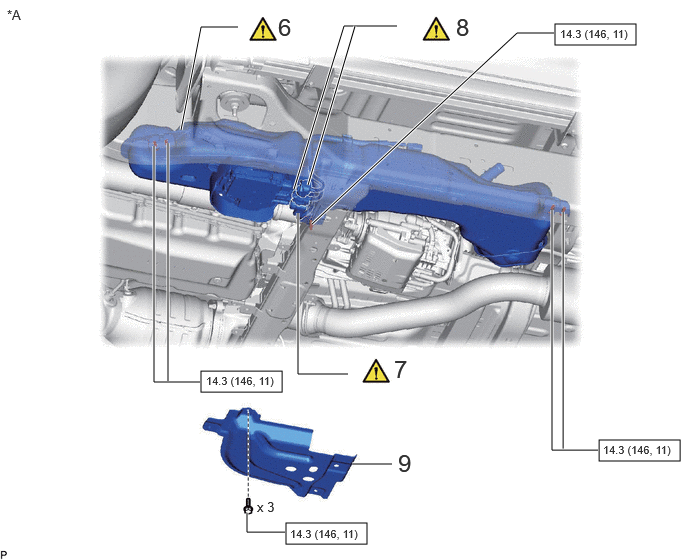
6 UREA TANK SUB-ASSEMBLY 77801A (Click here) - -
7 UREA TUBE WITH HEATER ASSEMBLY 77840A (Click here) - -
8 INSTALL UREA TANK HARNESS 77885 (Click here) - -
9 UREA TANK PROTECTOR 77851A - - -

*A w/ Urea SCR System - -
V100146

N*m (kgf*cm, ft.*lbf): Specified torque
V103638

Do not apply lubricants

C463220N04
5.542,2 7,3.75 1.458,1.75 5.5,3.75 7,5.5 1.5,1.75 2.917,0.042 4.74,1.323 1.823,1.281 3.198,1.01 4.083,1.229 0.885,0.219 6.344,1.688 7.052,1.917 0.708,0.229 4.792,2.708 5.521,2.938 0.729,0.229 5.667,3.385 6.448,3.646 0.781,0.26 6.156,4.865 6.938,5.125 0.781,0.26 4.052,3.792 4.833,4.052 0.781,0.26 1.958,3.688 2.74,3.948 0.781,0.26 2.917,2 2.917,1.583 2.917,1.583 3.083,1.583 true 3.823,0.615 3.823,0.281 3.823,0.281 3.99,0.281 true 6.458,1.052 6.458,0.635 6.458,0.635 6.625,0.635 true 6.281,2.271 6.115,2.271 6.115,2.271 6.115,2.594 true 5.167,1.583 5.167,1.167 5.167,1.167 5.333,1.167 true 5.958,5.323 5.792,5.323 5.792,5.323 5.792,4.323 true 2.875,3.583 2.708,3.583 2.708,3.583 2.625,3.208 true 2.167,4.833 2,4.833 2,4.833 2,4.167 true 0.583,3.167 0.583,2.75 0.583,2.75 0.75,2.75 true 4.094,1.125 4.365,1.125 true 6.344,1.792 6.125,1.792 6.125,1.792 6.26,1.625 true 4.792,2.823 4.688,2.823 4.688,2.823 4.688,2.646 true 1.948,3.813 1.781,3.813 1.781,3.813 1.781,3.635 true 6.469,3.531 6.688,3.531 6.688,3.531 6.51,3.177 false 4.052,3.917 3.885,3.917 3.885,3.917 3.885,3.25 true 6.521,4.865 6.521,4.677 false 0.813,2.656 1.125,2.854 0.313,0.198 10 false *2 2.229,4.76 2.542,4.958 0.313,0.198 10 false *1 1.615,4.542 1.969,4.74 0.354,0.198 10 false x 2 0.75,3.771 1.115,3.969 0.365,0.198 10 false x 2 1.885,3.49 2.26,3.688 0.375,0.198 10 false x 5 3.969,3.052 4.625,3.25 0.656,0.198 10 false x 6 (*A) 4.792,2.5 5.188,2.688 0.396,0.188 10 false x 4 6.406,1.417 6.771,1.604 0.365,0.188 10 false x 2 5.698,2.063 6.01,2.26 0.313,0.198 10 false *G 5.573,3.813 5.885,4.01 0.313,0.198 10 false *F 3.979,3.25 4.885,3.458 0.906,0.208 10 false x 4 (*B *D) 2.969,0.083 3.281,0.281 0.313,0.198 10 false *A 3.344,1.052 4.083,1.229 0.74,0.177 8 false 29 (296, 21) 6.646,0.49 7.073,0.813 0.427,0.323 18 false 10 5.406,1.021 5.833,1.344 0.427,0.323 18 false 11 6.344,2.115 6.771,2.438 0.427,0.323 18 false 12 5.99,5.156 6.417,5.479 0.427,0.323 18 false 12 4.031,0.156 4.458,0.479 0.427,0.323 18 false 13 3.135,1.458 3.563,1.781 0.427,0.323 18 false 14 2.927,3.438 3.354,3.76 0.427,0.323 18 false 15 3.979,3.448 4.844,3.667 0.865,0.219 10 false x 2 (*C *E) 6.604,4.542 6.958,4.74 0.354,0.198 10 false x 2 6.385,1.708 7.125,1.885 0.74,0.177 8 false 29 (296, 21) 4.865,2.74 5.604,2.917 0.74,0.177 8 false 29 (296, 21) 6.25,4.896 6.99,5.073 0.74,0.177 8 false 29 (296, 21) 5.75,3.438 6.49,3.615 0.74,0.177 8 false 29 (296, 21) 4.135,3.854 4.875,4.031 0.74,0.177 8 false 29 (296, 21) 2.042,3.74 2.781,3.917 0.74,0.177 8 false 29 (296, 21)

Procedure Part Name Code
Z101186

Z101188

Z101187

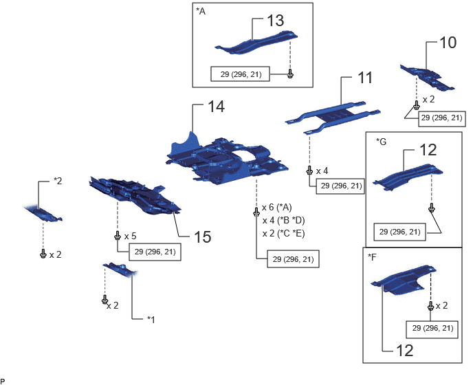
10 TRANSMISSION UNDER COVER ASSEMBLY 51470 - - -
11 OIL PAN PROTECTOR ASSEMBLY 51440 - - -
12 FRAME UNDER COVER ASSEMBLY LH 51450C - - -
13 FRAME UNDER COVER ASSEMBLY RH 51430A - - -
14 NO. 2 ENGINE UNDER COVER ASSEMBLY 51420 - - -
15 NO. 1 ENGINE UNDER COVER ASSEMBLY 51410 - - -

*A for V35A-FTS, w/ Cover *B for V35A-FTS, w/o Cover
*C for 1GR-FE *D for F33A-FTV, w/ Cover
*E for F33A-FTV, w/o Cover *F w/ Urea SCR system
*G w/o Urea SCR system - -
*1 ENGINE SIDE COVER SUB-ASSEMBLY LH *2 ENGINE SIDE COVER SUB-ASSEMBLY RH
V100146

N*m (kgf*cm, ft.*lbf): Specified torque - -

PROCEDURE

Hide 37140 1.INSTALL FRONT PROPELLER SHAFT ASSEMBLY

Z101186

NOTICE:

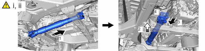
Refer to the components illustration for the installation direction of the propeller shaft.


a.

w/o Urea SCR System:

C458150N01
0.448,0.042 0.896,0.396 0.448,0.354 18 true i, ii 2.063,1.26 2.219,1.458 0.156,0.198 10 true 1 4.833,0.938 4.99,1.135 0.156,0.198 10 true 2 6.208,0.688 6.365,0.885 0.156,0.198 10 true 3 5.396,0.323 5.552,0.521 0.156,0.198 10 true 4

i.

Completely remove any oil, etc. and clean the contact surfaces of the 2 propeller shaft flanges, differential flange and transfer flange.


ii.

Temporarily install the front propeller shaft assembly to the transfer and differential in the order shown in the illustration.
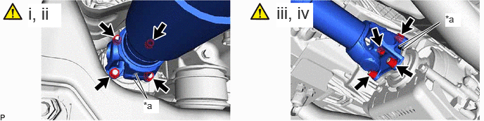


b.
C457903C02
5.906,0.688 6.51,0.333 6.51,0.333 5.969,0.729 true 2.01,1.094 2.177,1.458 2.177,1.458 1.979,1.177 true 0.417,0.052 0.906,0.406 0.49,0.354 18 true i, ii 4.094,0.042 4.635,0.406 0.542,0.365 18 true iii, iv 6.594,0.198 6.823,0.396 0.229,0.198 10 true *a 2.125,1.479 2.354,1.677 0.229,0.198 10 true *a
*a Matchmark - -


i.

Align the matchmarks on the propeller shaft flange and differential flange.


ii.

Install the front propeller shaft assembly with the 4 nuts and 4 washers.

Torque:
88.3 N*m (900 kgf*cm, 65 ft.*lbf)


iii.

Align the matchmarks on the propeller shaft flange and transfer flange.


iv.

Install the front propeller shaft assembly with the 4 nuts and 4 washers.

Torque:
88.3 N*m (900 kgf*cm, 65 ft.*lbf)


Hide 2.INSTALL NO. 2 PROPELLER SHAFT HEAT INSULATOR (w/o Urea SCR System)
a.
C458148C01
0.448,0.083 0.729,0.438 0.281,0.354 18 false i
V100136

Front of the Vehicle - -


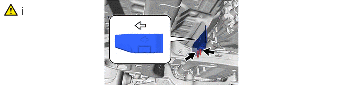
i.

Install the No. 2 propeller shaft heat insulator with the 2 bolts.

Torque:
15.7 N*m (160 kgf*cm, 12 ft.*lbf)

NOTICE:

Install so that the direction of the arrow points to the front of the vehicle.


Hide 77801A 3.SEPARATE UREA TANK SUB-ASSEMBLY (w/ Urea SCR System)

Z101186

(Click here)

Hide 4.INSTALL NO. 3 FRAME CROSSMEMBER ASSEMBLY (w/ Urea SCR System)
a.
C463232C03
2.604,0.813 2.76,1.01 0.156,0.198 10 false - 0.365,0.198 1.01,0.531 0.646,0.333 18 true ii 2.052,2.74 2.448,3.052 0.396,0.313 18 true i 3.781,0.115 4.469,0.458 0.688,0.344 18 true iii
V100135

Bolt
V100136

Nut


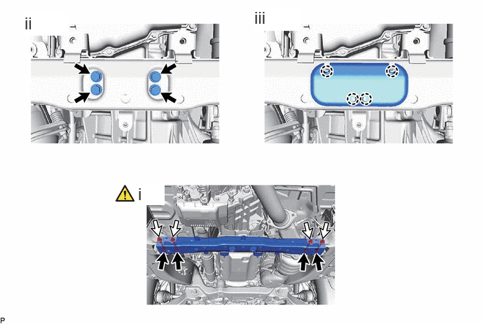
i.

Install the No. 3 frame crossmember assembly with the 4 nuts and 4 bolts.

Torque:
42 N*m (428 kgf*cm, 31 ft.*lbf)

NOTICE:

Make sure to install the nuts so that they are facing the rear of the vehicle.


HINT:

Hold the bolts to tighten the nuts.


ii.

Connect the rear engine mounting insulator to the No. 3 frame crossmember assembly with the 4 bolts.

Torque:
37 N*m (377 kgf*cm, 27 ft.*lbf)


iii.

Attach the claw and install the No. 3 engine mounting hole cover to the No. 3 frame crossmember assembly.


Hide 36179 5.INSTALL TRANSFER CASE LOWER PROTECTOR (w/ Urea SCR System)

Hide 77801A 6.CONNECT UREA TANK SUB-ASSEMBLY (w/ Urea SCR System)
a.
C463233N01
0.5,0.094 0.875,0.49 0.375,0.396 18 true i

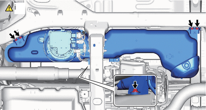
i.

Return the Urea tank sub-assembly to the proper mounting position, and install the Urea tank sub-assembly with 5 bolts.

Torque:
14.3 N*m (146 kgf*cm, 11 ft.*lbf)


Hide 77840A 7.INSTALL UREA TUBE WITH HEATER ASSEMBLY (w/ Urea SCR System)

Z101186

(Click here)

Hide 77885 8.INSTALL UREA TANK HARNESS (w/ Urea SCR System)

Z101186

(Click here)

Hide 77851A 9.INSTALL UREA TANK PROTECTOR (w/ Urea SCR System)

Torque:
14.3 N*m (146 kgf*cm, 11 ft.*lbf)

Hide 51470 10.INSTALL TRANSMISSION UNDER COVER ASSEMBLY (w/ Cover)

Hide 51450C 12.INSTALL FRAME UNDER COVER ASSEMBLY LH (for V35A-FTS, w/ Cover)

Hide 51430A 13.INSTALL FRAME UNDER COVER ASSEMBLY RH (for V35A-FTS)