Home › Drivetrain › AJA0F (AUTOMATIC TRANSMISSION / TRANSAXLE) › AUTOMATIC TRANSMISSION UNIT (for F33A-FTV) › from 2021.07
RM38G0E _52 Drivetrain _100435 AJA0F AUTOMATIC TRANSMISSION / TRANSAXLE _0484532 AUTOMATIC TRANSMISSION UNIT(for F33A-FTV) A

AJA0F AUTOMATIC TRANSMISSION / TRANSAXLE  AUTOMATIC TRANSMISSION UNIT(for F33A-FTV)  REASSEMBLY  


CAUTION / NOTICE / HINT
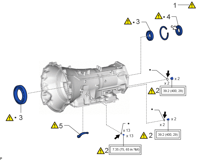
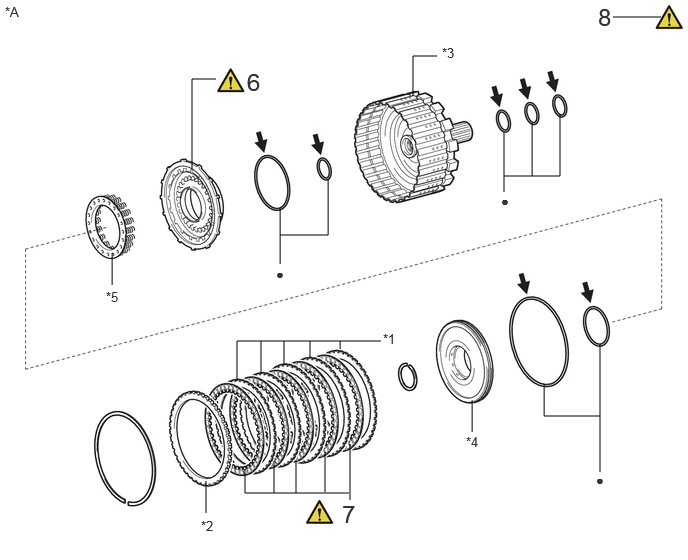
COMPONENTS (REASSEMBLY)
C460371C01
4.01,5.333 5.094,5.583 1.083,0.25 5.688,4.781 6.521,5.031 0.833,0.25 5.875,3.188 6.708,3.438 0.833,0.25 5.823,3.135 6.76,3.49 0.938,0.354 5.635,4.729 6.573,5.083 0.938,0.354 3.969,5.281 5.135,5.635 1.167,0.354 6.25,3.188 6.25,2.854 false 6.115,4.781 6.115,4.365 false 4.49,5.333 4.49,4.938 false 0.76,4.115 0.76,3.781 false 4.417,4.844 4.479,4.5 4.479,4.5 4.563,4.5 false 2.927,4.917 2.5,4.573 2.5,4.573 2.333,4.573 false 5.948,4.344 5.781,4.01 5.781,4.01 5.615,4.01 false 6.063,2.865 5.688,2.563 5.688,2.563 5.521,2.563 false 6.49,0.958 6.406,0.604 6.406,0.604 6.24,0.604 false 5.479,1.135 5.313,0.802 5.313,0.802 5.146,0.802 false 6.469,0.177 6.885,0.177 false 0.688,4.135 1.5,4.51 0.813,0.375 18 false 3 0.521,4.188 0.677,4.385 0.156,0.198 10 false ● 2.146,4.438 2.958,4.813 0.813,0.375 18 false 5 4.635,4.406 4.792,4.604 0.156,0.198 10 false ● 4.479,4.667 5.094,4.865 0.615,0.198 10 false x 13 4.594,4.865 5.208,5.063 0.615,0.198 10 false x 13 4.094,5.375 6.667,5.531 2.573,0.156 8 false 7.35 (75, 65 in.*lbf) 5.75,4.833 6.729,5.177 0.979,0.344 8 false 39.2 (400, 29) 3.813,5.333 4.063,5.74 0.25,0.406 18 false 2 5.417,4.781 5.781,5.24 0.365,0.458 18 false 2 5.49,3.885 5.646,4.083 0.156,0.198 10 false ● 5.938,3.24 6.917,3.583 0.979,0.344 8 false 39.2 (400, 29) 5.667,3.146 5.917,3.552 0.25,0.406 18 false 2 5.417,2.448 5.625,2.729 0.208,0.281 10 false ● 6.063,0.458 6.875,0.833 0.813,0.375 18 false 4 5.927,0.521 6.083,0.719 0.156,0.198 10 false ● 4.948,0.635 5.76,1.01 0.813,0.375 18 false 3 4.823,0.719 4.979,0.917 0.156,0.198 10 false ● 6.292,0.042 6.573,0.396 0.281,0.354 18 false 1 6.354,2.781 6.813,2.979 0.458,0.198 10 false x 2 5.979,2.948 6.438,3.146 0.458,0.198 10 false x 2 5.813,4.458 6.271,4.656 0.458,0.198 10 false x 2 6.229,4.25 6.688,4.448 0.458,0.198 10 false x 2

Procedure Part Name Code
Z101186

Z101188

Z101187

1 BEARING POSITION - (Click here) - -
2 AUTOMATIC TRANSMISSION CASE PLUG 35141B (Click here) - -
3 BALL BEARING 35701C (Click here) - -
4 TRANSMISSION CASE OIL SEAL 33111F (Click here) - -
5 BRAKE PLATE STOPPER SPRING 35639B (Click here) - -

V111893

Tightening torque for "Major areas involving basic vehicle performance such as moving/turning/stopping": N*m (kgf*cm, ft.*lbf) ● Non-reusable part
V100135

Toyota Genuine ATF WS
V100136

MP grease

C456991C01
5.25,1.833 5.833,1.833 5.833,1.833 5.833,1.188 false 5.25,2 5.25,1.375 false 5.542,1.833 5.542,1.281 false 4.302,1 4.302,0.583 4.302,0.583 4.552,0.583 false 2.917,2.448 3.417,2.448 3.417,2.448 3.417,1.865 false 2.917,2.75 2.917,2.167 false 2,1.76 2,0.823 2,0.823 2.25,0.823 false 1.167,2.969 1.167,2.635 false 6.25,4.333 5.667,4.333 5.667,4.333 5.667,4 false 6.25,4.917 6.25,3.583 false 4.917,4.5 4.917,4.167 false 2.146,5.344 2.146,5.01 false 2.469,3.969 2.469,3.552 2.469,3.552 3.969,3.552 false 2.719,3.885 2.719,3.552 false 2.958,3.802 2.958,3.552 false 3.229,3.719 3.229,3.552 false 3.542,3.635 3.542,3.552 false 2.552,4.885 2.552,5.135 2.552,5.135 3.635,5.135 false 2.854,5.135 2.854,4.802 false 3.083,5.135 3.083,4.802 false 3.385,5.125 3.385,4.708 false 3.646,5.208 3.646,4.625 false 6.385,0.177 6.885,0.177 false 5.219,2.01 5.375,2.208 0.156,0.198 10 false ● 1.104,3.01 1.417,3.208 0.313,0.198 10 false *5 2.875,2.771 3.031,2.969 0.156,0.198 10 false ● 2.094,5.396 2.406,5.594 0.313,0.198 10 false *2 3.99,3.448 4.302,3.646 0.313,0.198 10 false *1 6.208,4.917 6.365,5.115 0.156,0.198 10 false ● 2.573,0.708 2.896,1.125 0.323,0.417 18 false 6 3.563,5.208 3.885,5.625 0.323,0.417 18 false 7 6.229,0.031 6.552,0.448 0.323,0.417 18 false 8 0.052,0.042 0.365,0.24 0.313,0.198 10 false *A 4.854,4.521 5.167,4.719 0.313,0.198 10 false *4 4.604,0.469 4.917,0.667 0.313,0.198 10 false *3

Procedure Part Name Code
Z101186

Z101188

Z101187

6 C-4 CLUTCH PISTON 35638 (Click here) - -
7 NO. 4 CLUTCH DISC 35883C (Click here) - -
8 INSPECT PISTON STROKE OF NO. 4 CLUTCH - (Click here) - -

*A REAR MULTIPLE DISC CLUTCH ASSEMBLY - -
*1 NO. 4 CLUTCH PLATE *2 CLUTCH FLANGE
*3 OUTPUT SHAFT ASSEMBLY *4 C-4 CLUTCH BALANCER
*5 FORWARD CLUTCH RETURN SPRING SUB-ASSEMBLY (C-4 CLUTCH) - -
● Non-reusable part
V100135

Toyota Genuine ATF WS

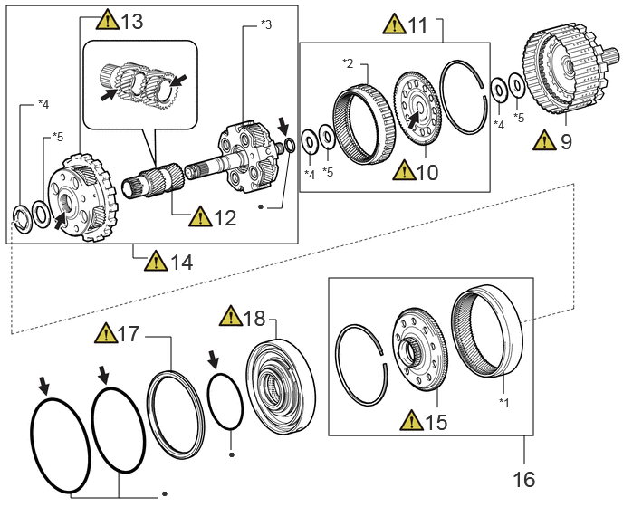
C468575C01
3.448,0.49 5.635,2.208 2.188,1.719 3.781,3.198 6.135,5.01 2.354,1.813 0.073,0.063 3.427,2.802 3.354,2.74 1.979,2.125 1.979,2.469 1.979,2.469 2.198,2.469 false 4.896,1.813 4.896,1.615 false 5.01,0.219 5.094,0.219 5.094,0.219 5.094,0.5 false 3.771,1.854 3.771,1.688 false 3.333,1.74 3.24,2.396 3.24,2.396 3.073,2.396 false 5.031,4.688 5.031,4.438 false 5.792,4.531 5.792,4.281 false 6.031,5.344 6.031,5.01 false 0.813,5.646 0.813,5.729 0.813,5.729 1.813,5.729 false 1.365,5.729 1.365,5.396 false 2.656,5.177 2.656,4.927 false 0.917,1.781 0.917,0.198 0.917,0.198 1.167,0.198 false 3.563,1.906 3.563,1.74 false 0.583,1.583 0.5,1.583 0.5,1.583 0.5,2.333 false 0.396,1.208 0.229,1.208 0.229,1.208 0.229,2.375 false 6.51,1.448 6.51,1.281 false 3.094,3.677 3.177,3.677 3.177,3.677 3.177,3.906 false 4.146,0.74 4.229,0.74 4.229,0.74 4.229,0.969 false 1.667,3.875 1.969,3.875 1.969,3.875 1.969,4.292 false 2.958,0.302 2.792,0.302 2.792,0.302 2.792,1.469 false 1.531,2.802 1.531,2.969 1.531,2.969 1.698,2.969 false 5.74,1.323 5.74,1.156 false 5.948,1.271 5.948,1.104 false 4.677,0.135 5.271,0.573 0.594,0.438 18 false 11 6.448,1.479 6.865,1.875 0.417,0.396 18 false 9 4.771,1.833 5.135,2.188 0.365,0.354 18 false 10 2.448,2.354 2.813,2.698 0.365,0.344 18 false 12 1.375,0.094 1.885,0.49 0.51,0.396 18 false 13 2.958,2.281 3.208,2.49 0.25,0.208 10 false ● 1.948,2.865 2.323,3.229 0.375,0.365 18 false 14 3,0.198 3.313,0.396 0.313,0.198 10 false *3 0.438,1.115 0.75,1.313 0.313,0.198 10 false *4 4.875,4.708 5.25,5.073 0.375,0.365 18 false 15 1.333,3.688 1.698,3.979 0.365,0.292 18 false 17 1.854,5.583 2.104,5.792 0.25,0.208 10 false ● 2.625,5.135 2.875,5.344 0.25,0.208 10 false ● 3.708,1.896 4.021,2.094 0.313,0.198 10 false *5 5.885,5.365 6.25,5.656 0.365,0.292 18 false 16 5.74,4.552 6.052,4.75 0.313,0.198 10 false *1 5.906,1.271 6.219,1.469 0.313,0.198 10 false *5 0.604,1.49 0.917,1.688 0.313,0.198 10 false *5 2.781,3.51 3.26,3.844 0.479,0.333 18 false 18 3.938,0.646 4.25,0.844 0.313,0.198 10 false *2 3.5,1.927 3.813,2.125 0.313,0.198 10 false *4 5.677,1.354 5.99,1.552 0.313,0.198 10 false *4

Procedure Part Name Code
Z101186

Z101188

Z101187

9 REAR MULTIPLE DISC CLUTCH ASSEMBLY 35650 (Click here) - -
10 REAR PLANETARY RING GEAR FLANGE 35762 (Click here) - -
11 REAR PLANETARY RING GEAR WITH REAR PLANETARY RING GEAR FLANGE 35761 (Click here) - -
12 PLANETARY SUN GEAR SUB-ASSEMBLY 35706H (Click here) - -
13 CENTER PLANETARY GEAR ASSEMBLY 35750 (Click here) - -
14 REAR PLANETARY GEAR ASSEMBLY WITH PLANETARY SUN GEAR SUB-ASSEMBLY AND CENTER PLANETARY GEAR ASSEMBLY 35760 (Click here) - -
15 CENTER PLANETARY RING GEAR FLANGE 35769 (Click here) - -
16 CENTER PLANETARY RING GEAR WITH CENTER PLANETARY RING GEAR FLANGE 35763 - - -
17 1ST AND REVERSE BRAKE PISTON 35623S (Click here) - -
18 CENTER SUPPORT ASSEMBLY 35620 (Click here) - -

*1 CENTER PLANETARY RING GEAR *2 REAR PLANETARY RING GEAR
*3 REAR PLANETARY GEAR ASSEMBLY *4 THRUST NEEDLE ROLLER BEARING
*5 THRUST BEARING RACE - -
● Non-reusable part
V100135

Toyota Genuine ATF WS

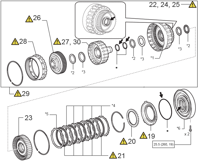
C456993C02
0.031,0.031 7.146,3.156 7.115,3.125 5.521,5.104 6.313,5.354 0.792,0.25 5.458,4.74 5.458,4.49 false 3.917,5.635 2.333,5.635 2.333,5.635 2.333,5.25 false 3.271,4.854 3.271,4.438 false 2.667,5.635 2.667,5.167 false 2.406,4.583 2.406,3.833 2.406,3.833 3.99,3.833 false 2.667,4.469 2.667,3.844 false 3.323,4.323 3.323,3.844 false 3,4.396 3,3.844 false 2.646,2.521 2.646,2.271 false 4.229,1.979 4.563,1.979 4.563,1.979 4.563,1.729 false 4.229,2.333 4.229,1.833 false 4.833,2.042 4.833,1.708 false 5.146,2.01 5.146,1.677 false 1.521,0.74 1.688,0.74 1.688,0.74 1.938,1.927 false 2.958,1.542 3.125,1.542 3.125,1.542 3.26,1.698 false 1.01,1.51 1.177,1.51 1.177,1.51 1.302,1.969 false 3,2.458 3,2.208 false 6.552,0.156 6.885,0.156 false 0.51,3.406 0.344,3.406 0.344,3.406 0.344,3.156 false 6.323,5.24 6.906,5.24 6.906,5.24 6.906,4.729 false 6.052,4.635 6.052,4.302 false 3.667,4.219 3.667,3.844 false 3,5.635 3,5.083 false 3.333,5.635 3.333,5 false 3.667,5.625 3.667,4.917 false 0.677,4.927 0.677,4.26 0.677,4.26 0.844,4.26 false 4.76,4.958 4.76,4.552 false 1.792,4.156 2.042,4.156 2.042,4.156 2.042,4.656 false 6.802,1.51 6.802,1.177 false 6.49,1.604 6.49,1.271 false 5.604,2.115 5.771,2.115 5.771,2.115 5.896,1.76 false 6.583,4.667 6.667,4.667 6.667,4.667 6.667,4.333 false 4.635,4.969 5.135,5.292 0.5,0.323 18 false 20 0.896,4.115 1.292,4.448 0.396,0.333 18 false 23 1.198,0.49 1.583,0.99 0.385,0.5 18 false 26 5.396,0.01 6.719,0.594 1.323,0.583 18 false 22, 24, 25 1.625,4.042 1.938,4.24 0.313,0.198 10 false *5 2.229,1.365 3.052,1.74 0.823,0.375 18 false 27, 30 4.177,2.354 4.333,2.552 0.156,0.198 10 false ● 4.771,2.031 5.083,2.229 0.313,0.198 10 false *2 5.083,2.052 5.396,2.25 0.313,0.198 10 false *3 5.448,2.01 5.76,2.208 0.313,0.198 10 false *1 0.792,3.24 1.281,3.625 0.49,0.385 18 false 29 0.698,1.344 1.083,1.844 0.385,0.5 18 false 28 2.563,2.552 2.875,2.75 0.313,0.198 10 false *2 2.958,2.521 3.271,2.719 0.313,0.198 10 false *3 5.563,5.156 6.417,5.51 0.854,0.354 8 false 25.5 (260, 19) 6.021,4.646 6.344,4.948 0.323,0.302 10 false ● 4.042,3.74 4.354,3.938 0.313,0.198 10 false *4 6.75,1.573 7.063,1.771 0.313,0.198 10 false *2 6.448,1.688 6.76,1.885 0.313,0.198 10 false *3 6.396,4.563 6.708,4.76 0.313,0.198 10 false *6 6.677,4.771 7.135,4.969 0.458,0.198 10 false x 2 5.333,4.781 5.833,5.104 0.5,0.323 18 false 19 4.26,5.49 4.76,5.813 0.5,0.323 18 false 21

Procedure Part Name Code
Z101186

Z101188

Z101187

19 NO. 2 BRAKE PISTON 35622G (Click here) - -
20 BRAKE PISTON RETURN SPRING SUB-ASSEMBLY 35608A (Click here) - -
21 NO. 2 BRAKE DISC 35682A (Click here) - -
22 INSPECT PISTON STROKE OF NO. 2 BRAKE 35682A (Click here) - -
23 C-3 CLUTCH ASSEMBLY 35640 - - -
24 INSPECT PISTON STROKE OF NO. 3 CLUTCH 35640 (Click here) - -
25 INSPECT PISTON STROKE OF C-1 CLUTCH ASSEMBLY 35610 (Click here) - -
26 C-2 CLUTCH ASSEMBLY 35650L (Click here) - -
27 INSTALL C-2 DRUM SUB-ASSEMBLY 3560B (Click here) - -
28 FRONT PLANETARY RING GEAR 35743 (Click here) - -
29 FRONT PLANETARY RING GEAR WITH C-1 CLUTCH ASSEMBLY 35743 (Click here) - -
30 INSPECT PISTON STROKE OF C-2 CLUTCH DRUM SUB-ASSEMBLY 3560B (Click here) - -

*1 C-1 CLUTCH ASSEMBLY *2 THRUST NEEDLE ROLLER BEARING
*3 THRUST BEARING RACE *4 NO. 2 BRAKE PLATE
*5 NO. 2 BRAKE FLANGE *6 CENTER SUPPORT ASSEMBLY WITH 1ST AND REVERSE BRAKE PISTON
V100146

N*m (kgf*cm, ft.*lbf): Specified torque ● Non-reusable part
V100135

Toyota Genuine ATF WS - -

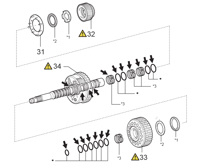
C459136C02
1.917,5.583 3.75,5.583 3.75,5.583 3.75,5 false 3.521,5.583 3.521,5.083 false 3.354,5.583 3.354,5.167 false 3.198,5.583 3.198,5.167 false 2.979,5.583 2.979,5.25 false 2.76,5.583 2.76,5.25 false 2.323,5.583 2.323,5.365 false 4.146,5.375 4.146,4.958 false 5.333,2.75 5.333,2.5 false 5.604,4.917 5.604,4.667 false 4.938,5.292 4.938,5.042 false 6.115,4.76 6.115,4.51 false 2.208,2.313 2.375,2.313 2.375,2.313 2.719,2.552 false 5.5,2.75 5.167,2.75 5.167,2.75 5.167,2.531 false 5.25,3 4.667,3 4.667,3 4.667,2.667 false 4.917,3 4.917,2.583 false 4.354,3.25 4.354,2.75 false 4.688,3.25 4.104,3.25 4.104,3.25 4.104,2.833 false 4.188,3.625 3.885,3.625 3.885,3.625 3.885,2.875 false 1.406,1.625 1.406,1.208 false 1.906,1.313 1.906,0.896 false 2.396,1.188 2.396,0.771 false 3.167,1.01 3.167,0.594 false 1.792,5.469 1.948,5.667 0.156,0.198 10 false ● 4.083,5.406 4.396,5.604 0.313,0.198 10 false *3 1.281,1.646 1.844,1.948 0.563,0.302 18 false 31 5.573,4.927 5.885,5.125 0.313,0.198 10 false *2 6.073,4.781 6.385,4.979 0.313,0.198 10 false *1 1.854,2.146 2.26,2.479 0.406,0.333 18 false 34 5.542,2.635 5.698,2.833 0.156,0.198 10 false ● 5.313,2.906 5.625,3.104 0.313,0.198 10 false *3 4.208,3.521 4.521,3.719 0.313,0.198 10 false *3 2.313,1.208 2.625,1.406 0.313,0.198 10 false *1 1.844,1.344 2.156,1.542 0.313,0.198 10 false *2 4.74,3.135 4.896,3.333 0.156,0.198 10 false ● 3.031,1.031 3.438,1.365 0.406,0.333 18 false 32 4.854,5.313 5.26,5.646 0.406,0.333 18 false 33

Procedure Part Name Code
Z101186

Z101188

Z101187

31 FRONT PLANETARY OIL RECEIVER 35753B - - -
32 FRONT PLANETARY SUN GEAR SUB-ASSEMBLY 35706P (Click here) - -
33 PLANETARY SUN GEAR ASSEMBLY 35710G (Click here) - -
34 FRONT PLANETARY GEAR ASSEMBLY 35720 (Click here) - -

*1 THRUST BEARING RACE *2 THRUST NEEDLE ROLLER BEARING
*3 NEEDLE ROLLER BEARING - -
● Non-reusable part
V100135

Toyota Genuine ATF WS

C459134C02
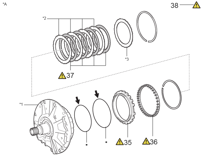
1.667,0.667 3.333,0.667 3.333,0.667 3.333,1 false 5.417,4.844 5.417,4.083 false 2.917,1.083 2.917,0.667 false 2.5,1.167 2.5,0.667 false 2.083,1.25 2.083,0.667 false 2.5,2.333 3.75,2.333 3.75,2.333 3.75,1.833 false 3.333,2.333 3.333,1.917 false 2.917,2.333 2.917,2.083 false 2.5,2.5 2.5,2.167 false 4.5,2 4.5,1.667 false 3.75,4.927 3.75,4.51 false 4.531,4.885 4.531,4.354 false 3.073,5.073 3.073,4.656 false 0.854,3.729 1.354,3.729 false 6.375,0.167 6.875,0.167 false 0.094,0.063 0.406,0.26 0.313,0.198 10 false *A 1.51,0.563 1.823,0.76 0.313,0.198 10 false *2 0.688,3.625 1,3.823 0.313,0.198 10 false *1 4.438,2.021 4.75,2.219 0.313,0.198 10 false *3 3.729,4.958 4.042,5.156 0.313,0.198 10 false ● 3.031,5.052 3.344,5.25 0.313,0.198 10 false ● 6.052,0.042 6.604,0.396 0.552,0.354 18 false 38 4.396,4.917 4.948,5.271 0.552,0.354 18 false 35 5.313,4.896 5.865,5.25 0.552,0.354 18 false 36 2.354,2.531 2.906,2.885 0.552,0.354 18 false 37

Procedure Part Name Code
Z101186

Z101188

Z101187

35 NO. 1 BRAKE PISTON 35621 (Click here) - -
36 BRAKE PISTON RETURN SPRING SUB-ASSEMBLY (NO. 1 BRAKE) 35608J (Click here) - -
37 NO. 1 BRAKE DISC 35681A (Click here) - -
38 INSPECT PISTON STROKE OF NO. 1 BRAKE 35681A (Click here) - -

*A STATOR SHAFT ASSEMBLY - -
*1 FRONT SUPPORT SUB-ASSEMBLY *2 NO. 1 BRAKE PLATE
*3 NO. 1 BRAKE FLANGE - -
● Non-reusable part
V100135

Toyota Genuine ATF WS

C456979C02
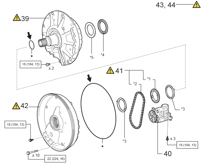
1.583,5.521 2.333,5.771 0.75,0.25 0.167,4.302 0.917,4.552 0.75,0.25 0.708,2.167 1.458,2.417 0.75,0.25 6.271,5.031 7.021,5.281 0.75,0.25 1.031,0.646 1.677,0.646 false 1.021,3.802 1.406,3.802 false 3.667,1.833 3.667,1.167 false 3.25,1.917 3.25,1.333 false 1.125,1.917 1.125,1.75 false 4.417,4.906 4.417,3.906 false 5.76,5.469 5.594,5.469 5.594,5.469 5.594,4.302 false 5,3.333 5,3 5,3 4.917,3 false 5.5,3.167 5.5,2.833 5.5,2.833 5.417,2.833 false 5.167,2.833 5.083,2.833 5.083,2.833 5.083,2.5 false 4.667,3 4.583,3 4.583,3 4.583,2.5 false 5.083,2.5 4.417,2.5 false 6.385,3.906 6.219,3.906 6.219,3.906 6.094,3.469 false 1.583,5.667 1,5.667 1,5.667 1,5.469 false 1.083,5 1.083,4.417 1.083,4.417 0.917,4.417 false 1.458,2.292 1.625,2.292 false 6.229,0.156 6.875,0.156 false 6.271,5.156 5.938,5.156 5.938,5.156 5.938,4.99 false 3.635,5.094 3.635,4.927 false 1.146,5.438 1.76,5.635 0.615,0.198 10 false x 10 5.813,5.313 6.365,5.667 0.552,0.354 18 false 40 1.083,1.896 1.24,2.094 0.156,0.198 10 false ● 4.354,4.938 4.667,5.135 0.313,0.198 10 false *3 4.729,2.896 5.042,3.094 0.313,0.198 10 false *2 5.219,2.719 5.531,2.917 0.313,0.198 10 false *1 0.75,0.51 1.135,0.865 0.385,0.354 18 false 39 6.427,3.792 6.74,3.99 0.313,0.198 10 false *3 3.188,1.958 3.5,2.156 0.313,0.198 10 false *5 3.573,1.865 3.885,2.063 0.313,0.198 10 false *4 1.677,5.573 2.667,5.76 0.99,0.188 8 false 22 (224, 16) 0.24,4.354 1.708,4.51 1.469,0.156 8 false 18 (184, 13) 1.729,2.344 2.188,2.542 0.458,0.198 10 false x 2 5.531,0.021 6.344,0.573 0.813,0.552 18 false 43, 44 0.781,2.208 1.74,2.448 0.958,0.24 8 false 18 (184, 13) 6.344,5.083 7.063,5.49 0.719,0.406 8 false 18 (184, 13) 6.042,4.844 6.5,5.042 0.458,0.198 10 false x 3 3.594,5.104 3.75,5.302 0.156,0.198 10 false ● 4.094,2.365 4.646,2.719 0.552,0.354 18 false 41 0.729,3.604 1.281,3.958 0.552,0.354 18 false 42

Procedure Part Name Code
Z101186

Z101188

Z101187

39 STATOR SHAFT ASSEMBLY 35370 (Click here) - -
40 OIL PUMP ASSEMBLY WITH DRIVEN SPROCKET - - - -
41 DRIVE SPROCKET AND TRANSMISSION DRIVE CHAIN - (Click here) - -
42 NO. 2 FRONT OIL PUMP COVER SUB-ASSEMBLY 35308K (Click here) - -
43 INSPECT INPUT SHAFT END PLAY - (Click here) - -
44 INSPECT INDIVIDUAL PISTON OPERATION - (Click here) - -

*1 DRIVE SPROCKET *2 TRANSMISSION DRIVE CHAIN
*3 GEAR THRUST WASHER *4 THRUST NEEDLE ROLLER BEARING
*5 THRUST BEARING RACE - -
V100146

N*m (kgf*cm, ft.*lbf): Specified torque ● Non-reusable part
V100135

Toyota Genuine ATF WS - -

C460372C01
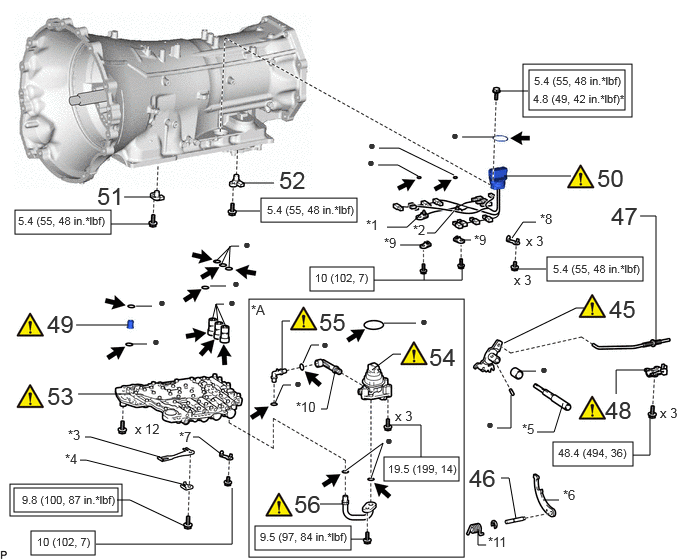
0.146,5.083 1.229,5.333 1.083,0.25 0.104,5.042 1.271,5.375 1.167,0.333 2.594,3.115 4.833,5.802 2.24,2.688 0.156,2.188 1.156,2.438 1,0.25 2.719,2.063 3.719,2.313 1,0.25 5.51,0.729 6.51,1.146 1,0.417 5.448,0.667 6.583,1.219 1.135,0.552 0.323,5.531 0.99,5.781 0.667,0.25 2.656,5.479 3.656,5.729 1,0.25 5.76,4.604 6.594,4.854 0.833,0.25 4,4.76 4.781,5.01 0.781,0.25 3.229,2.781 3.896,3.031 0.667,0.25 5.698,2.677 6.698,2.927 1,0.25 0.792,3.385 1.333,3.385 false 2.208,3.344 2.25,3.167 2.25,3.167 2.333,3.167 false 2.271,3.365 2.25,3.167 false 2.354,3.406 2.25,3.167 false 1.219,5.208 1.354,5.208 1.354,5.208 1.948,5.49 false 2.302,2.76 2.396,2.563 false 1.417,3.188 1.583,3.188 false 1.365,3.583 1.531,3.583 false 1.292,2.052 1.625,2.052 false 2.521,1.906 2.854,1.906 false 1.156,2.333 1.573,2.333 false 2.458,2.198 2.708,2.198 false 5.167,0.948 5.5,0.948 false 4,3.365 4.333,3.365 false 3.948,1.542 4.156,1.542 4.156,1.542 4.729,1.823 false 0.813,4.104 1.365,4.104 false 2.24,2.729 2.406,2.563 2.406,2.563 2.49,2.563 false 2.385,2.792 2.396,2.573 false 4.813,1.427 5.146,1.427 false 5.25,1.833 5.948,1.833 false 3.875,3.854 4.094,3.688 4.094,3.688 4.177,3.688 false 4.385,4.76 4.385,4.427 4.385,4.427 4.052,4.427 false 5.177,4.458 5.323,4.458 5.323,4.458 5.323,4.115 false 5.417,3.865 5.583,3.865 false 5.594,4.5 5.771,4.5 5.771,4.5 5.865,4.198 false 3.344,4.26 3.406,4.26 3.406,4.26 3.49,3.865 false 5.333,2.479 5.448,2.313 5.448,2.313 5.583,2.313 false 6.417,4.104 6.417,3.854 6.417,3.854 6.74,3.854 false 6.594,4.74 6.771,4.74 6.771,4.74 6.771,4.313 false 5.219,4.979 5.302,4.979 5.302,4.979 5.375,5.406 false 0.833,4.792 0.896,4.792 0.896,4.792 1.938,5.052 false 6.667,2.25 6.833,2.25 6.833,2.25 6.833,3.583 false 2.188,2.979 2.354,2.979 false 1,5.667 2.417,5.667 2.417,5.667 2.417,5.083 false 5.656,5.208 5.823,5.208 false 3.938,1.719 4.146,1.719 4.146,1.719 4.354,1.833 false 2.01,4.552 2.073,4.552 2.073,4.552 2.302,4.729 false 0.885,4.552 0.948,4.552 0.948,4.552 1.667,4.76 false 2.865,4.198 2.948,4.01 2.948,4.01 3.031,4.01 false 3.156,3.781 3.24,3.594 3.24,3.594 3.323,3.594 false 3.656,5.615 3.823,5.615 false 3.594,4.906 3.99,4.615 3.99,4.615 3.865,4.979 true 5.25,3.573 6,3.208 6,3.208 6.083,3.208 false 4.167,2.552 4.417,2.552 false 4.792,2.5 4.906,2.5 false 3.896,2.917 4.813,2.917 4.813,2.917 4.813,2.75 false 4.417,2.917 4.417,2.833 false 2.938,3.844 2.938,3.344 2.938,3.344 3.021,3.344 false 3.333,5.25 3.563,5.25 false 4.031,2.365 4.24,2.365 4.24,2.365 4.385,2.229 false 4.448,2.427 4.531,2.427 4.531,2.427 4.729,2.198 true 5.365,2.802 5.688,2.802 false 4.979,5.51 4.979,5.677 4.979,5.677 5.063,5.677 false 6.365,2.104 6.792,2.448 0.427,0.344 18 false 47 2.375,3.063 2.531,3.26 0.156,0.198 10 false ● 0.229,5.135 1.615,5.427 1.385,0.292 8 false 9.8 (100, 87 in.*lbf) 4.698,1.323 4.917,1.583 0.219,0.26 10 false ● 1.406,4.385 2.021,4.583 0.615,0.198 10 false x 12 1.646,3.063 1.802,3.26 0.156,0.198 10 false ● 1.583,3.469 1.74,3.667 0.156,0.198 10 false ● 0.49,3.229 1.042,3.583 0.552,0.354 18 false 49 6.219,1.708 6.771,2.063 0.552,0.354 18 false 50 0.188,2.229 1.26,2.531 1.073,0.302 8 false 5.4 (55, 48 in.*lbf) 2.781,2.115 3.854,2.417 1.073,0.302 8 false 5.4 (55, 48 in.*lbf) 5.552,0.958 6.583,1.333 1.031,0.375 8 false 4.8 (49, 42 in.*lbf)* 5.563,0.771 6.635,1.073 1.073,0.302 8 false 5.4 (55, 48 in.*lbf) 4.375,3.26 4.531,3.458 0.156,0.198 10 false ● 3.833,1.427 4.052,1.656 0.219,0.229 10 false ● 2.531,2.458 2.688,2.656 0.156,0.198 10 false ● 4.042,4.813 4.875,5.052 0.833,0.24 8 false 19.5 (199, 14) 5.625,3.76 5.781,3.958 0.156,0.198 10 false ● 5.063,4.333 5.344,4.635 0.281,0.302 10 false ● 2.708,5.521 4.094,5.729 1.385,0.208 8 false 9.5 (97, 84 in.*lbf) 2.615,3.146 2.927,3.344 0.313,0.198 10 false *A 4.885,4.833 5.438,5.188 0.552,0.354 18 false 46 6.875,4.219 7.156,4.479 0.281,0.26 10 false x 3 5.813,4.646 6.688,4.979 0.875,0.333 8 false 48.4 (494, 36) 0.385,5.573 1.302,5.802 0.917,0.229 8 false 10 (102, 7) 6.344,3.073 6.896,3.427 0.552,0.354 18 false 45 2.417,2.865 2.573,3.063 0.156,0.198 10 false ● 5.479,2.427 6.094,2.625 0.615,0.198 10 false x 3 5.354,2.833 5.969,3.031 0.615,0.198 10 false x 3 4.115,4.25 4.729,4.448 0.615,0.198 10 false x 3 3.823,1.604 3.979,1.802 0.156,0.198 10 false ● 1.865,4.469 2.146,4.729 0.281,0.26 10 false *7 0.708,4.448 0.99,4.708 0.281,0.26 10 false *3 0.677,4.698 0.958,4.958 0.281,0.26 10 false *4 3.083,4.156 3.365,4.417 0.281,0.26 10 false *10 3.063,3.906 3.219,4.104 0.156,0.198 10 false ● 3.344,3.5 3.5,3.698 0.156,0.198 10 false ● 4.01,4.5 4.167,4.698 0.156,0.198 10 false ● 5.625,2.198 6.24,2.396 0.615,0.198 10 false *8 5.438,4.385 5.708,4.594 0.271,0.208 10 false *5 5.865,5.073 6.479,5.271 0.615,0.198 10 false *6 4,2.448 4.615,2.646 0.615,0.198 10 false *9 4.938,2.417 5.552,2.615 0.615,0.198 10 false *9 3.281,2.823 4.198,3.052 0.917,0.229 8 false 10 (102, 7) 6.302,4.125 6.896,4.479 0.594,0.354 18 false 48 1.01,1.896 1.563,2.25 0.552,0.354 18 false 51 0.49,3.979 1.042,4.333 0.552,0.354 18 false 53 4.469,3.573 5.021,3.927 0.552,0.354 18 false 54 3.813,2.26 4.427,2.458 0.615,0.198 10 false *1 4.302,2.313 4.917,2.51 0.615,0.198 10 false *2 5.76,2.729 6.833,3.031 1.073,0.302 8 false 5.4 (55, 48 in.*lbf) 5.083,5.563 5.698,5.76 0.615,0.198 10 false *11 3.063,5.104 3.615,5.458 0.552,0.354 18 false 56 2.906,1.729 3.458,2.083 0.552,0.354 18 false 52 3.323,3.208 3.875,3.563 0.552,0.354 18 false 55

Procedure Part Name Code
Z101186

Z101188

Z101187

45 MANUAL VALVE LEVER SUB-ASSEMBLY 35505 (Click here) - -
46 PARKING LOCK PAWL SHAFT 35556 - - -
47 PARKING LOCK ROD SUB-ASSEMBLY 35501 - - -
48 PARKING LOCK PAWL BRACKET 35595 (Click here) - -
49 TRANSMISSION OIL PIPE 33129F (Click here) - -
50 TRANSMISSION WIRE 82125J (Click here) - -
51 TRANSMISSION REVOLUTION SENSOR (NT) 89413N - - -
52 TRANSMISSION REVOLUTION SENSOR (SP2) 89413V - - -
53 TRANSMISSION VALVE BODY ASSEMBLY 35400A (Click here) - -
54 OIL PUMP WITH MOTOR ASSEMBLY 35300D (Click here) - -
55 NO. 3 TRANSMISSION OIL PIPE 33129H (Click here) - -
56 NO. 2 TRANSMISSION OIL PIPE 33129G (Click here) - -

*A w/ Stop And Start System - -
*1 NO. 1 ATF TEMPERATURE SENSOR *2 NO. 2 ATF TEMPERATURE SENSOR
*3 MANUAL DETENT SPRING SUB-ASSEMBLY *4 MANUAL DETENT SPRING COVER
*5 MANUAL VALVE LEVER SHAFT *6 PARKING LOCK PAWL
*7 WIRE HARNESS CLAMP *8 TRANSMISSION WIRE CLAMP
*9 LOCK PLATE *10 NO. 4 TRANSMISSION OIL PIPE
*11 SPRING - -
V111893

Tightening torque for "Major areas involving basic vehicle performance such as moving/turning/stopping": N*m (kgf*cm, ft.*lbf)
V100146

N*m (kgf*cm, ft.*lbf): Specified torque
* For use with union nut wrench ● Non-reusable part
V100135

Toyota Genuine ATF WS - -

C460373C03
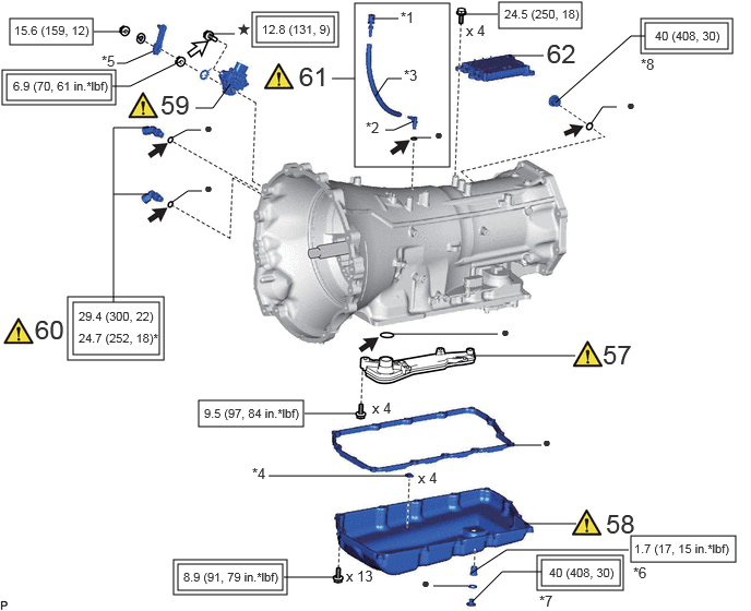
3.385,0.031 4.292,1.594 0.906,1.563 4.76,0.021 5.552,0.271 0.792,0.25 0.094,0.177 0.885,0.427 0.792,0.25 0.063,0.708 1.063,0.958 1,0.25 0.021,0.667 1.104,1 1.083,0.333 2.448,0.156 3.188,0.406 0.74,0.25 1.656,5.344 2.74,5.677 1.083,0.333 1.896,3.823 2.896,4.073 1,0.25 1.698,5.385 2.698,5.635 1,0.25 2.406,0.115 3.229,0.448 0.823,0.333 6.021,5.115 7.021,5.365 1,0.25 5.167,5.344 5.917,5.594 0.75,0.25 5.125,5.302 5.948,5.635 0.823,0.333 6.156,0.219 6.948,0.469 0.792,0.25 6.115,0.177 6.99,0.51 0.875,0.333 0.698,2.885 1.521,3.385 0.823,0.5 0.646,2.833 1.563,3.438 0.917,0.604 4.833,4.25 5.167,4.25 false 2.563,4.542 3.896,4.542 false 1.115,0.604 1.198,0.604 1.198,0.604 1.458,0.49 false 3.167,0.75 3.385,0.75 false 3.552,0.177 3.802,0.177 false 3.583,0.917 3.698,0.75 3.698,0.75 3.833,0.75 false 3.677,1.24 3.76,1.24 3.76,1.24 3.948,1.156 false 3.948,1.313 4.115,1.313 false 4.417,0.135 4.75,0.135 false 0.896,0.302 1.229,0.302 false 1.073,0.823 1.24,0.823 1.24,0.823 1.729,0.583 false 4.49,3.396 5.49,3.396 false 3.75,3.188 4.75,3.188 false 5,5 5.5,5 false 2.906,3.948 3.406,3.948 false 1.865,1.031 2.031,1.031 2.031,1.031 2.198,0.802 false 1.99,0.323 2.24,0.323 false 2.708,5.51 3.208,5.51 false 4.135,5.594 4.469,5.594 false 4.5,5.469 4.833,5.25 4.833,5.25 6,5.25 false 4.5,5.75 4.792,5.458 4.792,5.458 5.167,5.458 false 5.635,1.188 5.75,1.021 5.75,1.021 5.885,1.021 false 5.302,0.979 6.021,0.344 6.021,0.344 6.156,0.344 false 1.083,2.885 1.083,1.219 1.083,1.219 1.417,1.219 false 1.646,1.313 1.781,1.24 1.781,1.24 1.917,1.24 false 4.854,0.531 5.188,0.531 false 1.083,1.854 1.417,1.854 false 1.646,1.927 1.792,1.823 1.792,1.823 1.927,1.823 false 5.177,4.135 5.333,4.333 0.156,0.198 10 false ● 2.406,4.438 2.833,4.844 0.427,0.406 10 false *4 0.969,0.5 1.396,0.906 0.427,0.406 10 false *5 3.823,0.083 4.135,0.281 0.313,0.198 10 false *1 3.854,0.635 4.167,0.833 0.313,0.198 10 false *3 3.49,1.135 3.802,1.333 0.313,0.198 10 false *2 4.146,1.198 4.458,1.396 0.313,0.198 10 false ● 3.552,3.813 4.01,4.01 0.458,0.198 10 false x 4 3.302,5.417 3.76,5.615 0.458,0.198 10 false x 13 4.448,0.208 4.906,0.406 0.458,0.198 10 false x 4 4.813,0.063 5.885,0.271 1.073,0.208 8 false 24.5 (250, 18) 0.135,0.219 0.979,0.531 0.844,0.313 8 false 15.6 (159, 12) 0.125,0.75 1.281,0.969 1.156,0.219 8 false 6.9 (70, 61 in.*lbf) 4.781,3.083 4.938,3.281 0.156,0.198 10 false ● 5.219,0.365 5.677,0.854 0.458,0.49 18 false 62 5.75,3.24 6.333,3.688 0.583,0.448 18 false 57 2.5,0.208 3.365,0.5 0.865,0.292 8 false 12.8 (131, 9) 1.75,5.438 4.198,5.594 2.448,0.156 8 false 8.9 (91, 79 in.*lbf) 3.99,4.479 4.448,4.677 0.458,0.198 10 false x 4 1.948,3.875 4.396,4.031 2.448,0.156 8 false 9.5 (97, 84 in.*lbf) 5.781,4.854 6.365,5.302 0.583,0.448 18 false 58 1.531,0.854 2.115,1.302 0.583,0.448 18 false 59 2.26,0.198 2.417,0.396 0.156,0.198 10 false ★ 4.021,5.479 4.177,5.677 0.156,0.198 10 false ● 6.052,5.167 7.135,5.396 1.083,0.229 8 false 1.7 (17, 15 in.*lbf) 5.24,5.396 6,5.625 0.76,0.229 8 false 40 (408, 30) 5.979,0.917 6.292,1.115 0.313,0.198 10 false ● 6.25,0.271 7.156,0.479 0.906,0.208 8 false 40 (408, 30) 6.115,0.531 6.417,0.958 0.302,0.427 10 false *8 5.146,5.656 5.563,5.823 0.417,0.167 10 false *7 6.042,5.385 6.25,5.625 0.208,0.24 10 false *6 0.333,3 0.792,3.49 0.458,0.49 18 false 60 1.948,1.135 2.26,1.333 0.313,0.198 10 false ● 0.75,3.156 1.542,3.5 0.792,0.344 8 false 24.7 (252, 18)* 1.948,1.708 2.26,1.906 0.313,0.198 10 false ● 0.75,2.948 2.469,3.104 1.719,0.156 8 false 29.4 (300, 22) 2.854,0.583 3.313,1.073 0.458,0.49 18 false 61

Procedure Part Name Code
Z101186

Z101188

Z101187

57 VALVE BODY OIL STRAINER ASSEMBLY 35330 (Click here) - -
58 AUTOMATIC TRANSMISSION OIL PAN SUB-ASSEMBLY 35106 (Click here) - -
59 PARK/NEUTRAL POSITION SWITCH ASSEMBLY 84540 (Click here) - -
60 OIL COOLER TUBE UNION - (Click here) - -
61 BREATHER PLUG SUB-ASSEMBLY - (Click here) - -
62 TCM 89530C - - -

*1 NO. 1 BREATHER PLUG (ATM) *2 NO. 2 BREATHER PLUG (ATM)
*3 BREATHER PLUG HOSE *4 TRANSMISSION OIL CLEANER MAGNET
*5 TRANSMISSION CONTROL SHAFT LEVER RH *6 NO. 1 TRANSMISSION OIL FILLER TUBE
*7 OVERFLOW PLUG *8 REFILL PLUG
V111893

Tightening torque for "Major areas involving basic vehicle performance such as moving/turning/stopping": N*m (kgf*cm, ft.*lbf)
V100146

N*m (kgf*cm, ft.*lbf): Specified torque
* For use with union nut wrench ● Non-reusable part
V100135

Toyota Genuine ATF WS
V100136

Toyota Genuine Adhesive 1344
★ Precoated part - -

PROCEDURE

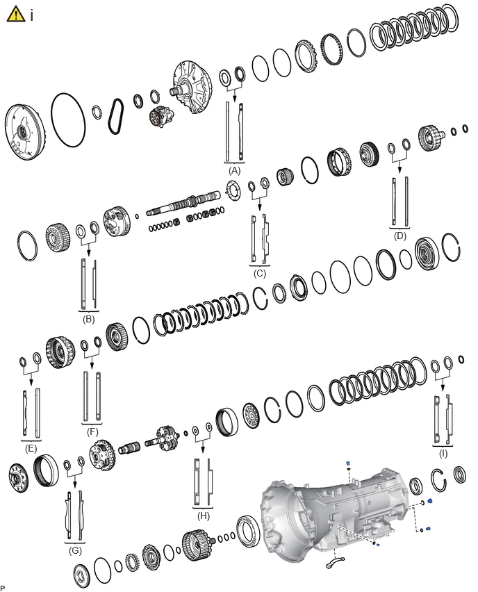
Hide 1. BEARING POSITION

a.
C460384N01
0.448,0.073 0.625,0.417 0.177,0.344 18 false i 3.427,2.469 3.656,2.698 0.229,0.229 10 false (A) 1.24,4.698 1.479,4.927 0.24,0.229 10 false (B) 3.802,4.01 4.042,4.25 0.24,0.24 10 false (C) 5.906,3.448 6.156,3.688 0.25,0.24 10 false (D) 0.375,6.635 0.615,6.844 0.24,0.208 10 false (E) 1.302,6.385 1.531,6.604 0.229,0.219 10 false (F) 1.031,8.167 1.302,8.417 0.271,0.25 10 false (G) 2.958,7.646 3.208,7.896 0.25,0.25 10 false (H) 6.583,6.708 6.802,6.969 0.219,0.26 10 false (I)

i.

Check each bearing position and installation direction.

Bearing Position:
Position Front Race Diameter
Inside/Outside
Thrust Bearing Diameter
Inside/Outside
Rear Race Diameter
Inside/Outside
(A) 67.10 mm (2.642 in.) / 92.60 mm (3.646 in.) 63.50 mm (2.500 in.) / 84.70 mm (3.335 in.) -
(B) - 38.30 mm (1.508 in.) / 58.10 mm (2.287 in.) 34.70 mm (1.366 in.) / 55.00 mm (2.165 in.)
(C) - 37.50 mm (1.476 in.) / 55.80 mm (2.197 in.) 38.20 mm (1.504 in.) / 59.67 mm (2.349 in.)
(D) - 47.60 mm (1.874 in.) / 63.80 mm (2.512 in.) 49.60 mm (1.953 in.) / 66.70 mm (2.626 in.)
(E) - 50.60 mm (1.992 in.) / 69.20 mm (2.724 in.) 54.20 mm (2.134 in.) / 76.10 mm (2.996 in.)
(F) 45.90 mm (1.807 in.) / 63.35 mm (2.494 in.) 45.90 mm (1.807 in.) / 62.10 mm (2.445 in.) -
(G) - 39.90 mm (1.571 in.) / 64.50 mm (2.539 in.) 38.90 mm (1.531 in.) / 68.20 mm (2.685 in.)
(H) - 22.70 mm (0.894 in.) / 48.40 mm (1.906 in.) 25.00 mm (0.984 in.) / 48.40 mm (1.906 in.)
(I) - 30.00 mm (1.181 in.) / 50.10 mm (1.972 in.) 31.83 mm (1.253 in.) / 52.11 mm (2.052 in.)


Hide 35141B 2.INSTALL AUTOMATIC TRANSMISSION CASE PLUG

HINT:

If automatic transmission fluid leaks from an automatic transmission case plug or the plug is corroded, replace it.
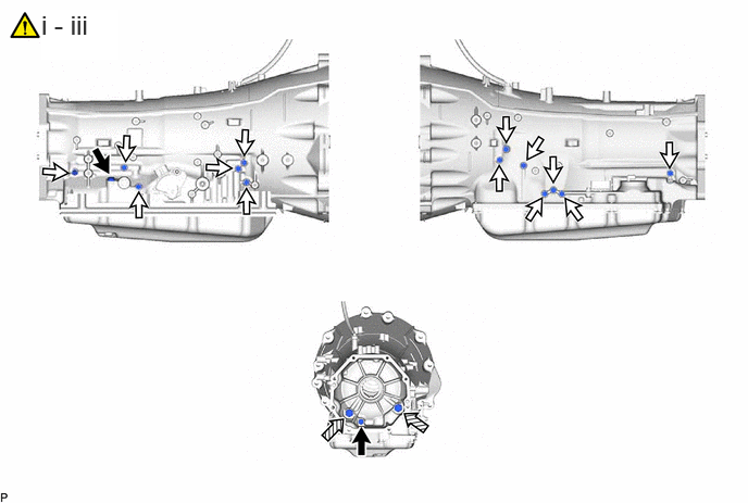

a.
C456925C02
0.396,0.094 1.135,0.573 0.74,0.479 18 true i - iii
V100135

for T55 "TORX"
V100136

for 12 mm head
V100137

for 24 mm head - -


i.

for T55 "TORX":

1. Coat 2 new O-rings with ATF.

2. Using a T55 "TORX" socket wrench, install the 2 automatic transmission case plugs and 2 O-rings to the automatic transmission case sub-assembly.

Torque:
39.2 N*m (400 kgf*cm, 29 ft.*lbf)


ii.

for 12 mm head:

1. Coat 13 new O-rings with ATF.

2. Install the 13 automatic transmission case plugs and 13 O-rings to the automatic transmission case sub-assembly.

Torque:
7.35 N*m (75 kgf*cm, 65 in.*lbf)


iii.

for 24 mm head:

1. Coat 2 new O-rings with ATF.

2. Install the 2 automatic transmission case plugs and 2 O-rings to the automatic transmission case sub-assembly.

Torque:
39.2 N*m (400 kgf*cm, 29 ft.*lbf)


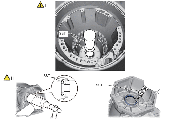
Hide 36701C 3.INSTALL BALL BEARING

a.
C459072N01
2.656,3.354 2.042,3.094 2.042,3.094 2.885,3.26 true 4.167,3.417 4.333,3.417 4.333,3.417 5.646,3.667 true 2.75,1.333 2.833,1.333 2.833,1.333 3.469,1.708 true 2.833,1.333 3.542,2.24 true 2.833,1.333 3.5,2.083 true 1.792,0.052 2.073,0.406 0.281,0.354 18 false i 0.438,2.99 0.719,3.344 0.281,0.354 18 false ii 1.75,2.958 2.208,3.156 0.458,0.198 10 false SST 3.865,3.333 4.323,3.531 0.458,0.198 10 false SST 2.385,1.26 2.74,1.479 0.354,0.219 10 true SST

i.

for Inside:

1. Using SST and a hammer, install a new ball bearing to the automatic transmission case sub-assembly.

SST
09502-24010  
09513-36040  
09308-14010  


ii.

for Outside:

1. Using SST and a hammer, install a new ball bearing to the automatic transmission case sub-assembly.

SST
09316-60012  (09316-00011, 09316-00021)

2. Using SST, install the snap ring to the automatic transmission case sub-assembly.

SST
09350-30020  (09350-07060)


Hide 33111F 4.INSTALL TRANSMISSION CASE OIL SEAL
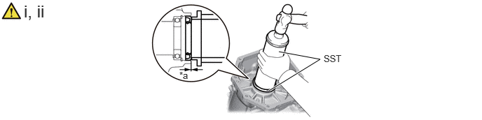
a.
C459076C01
4,1.354 4.76,0.885 4.76,0.885 4.146,0.771 true 0.354,0.021 1.729,0.375 1.375,0.354 18 false i, ii 2.667,1.042 2.865,1.198 0.198,0.156 10 false *a 4.813,0.792 5.26,1.156 0.448,0.365 10 false SST
*a 3.2 to 3.8 mm (0.126 to 0.150 in.) - -


i.

Using SST and a hammer, install a new transmission case oil seal to the automatic transmission case sub-assembly.

SST
09513-36040  
09502-12010  

Transmission Case Oil Seal Installation Depth:

3.2 to 3.8 mm (0.126 to 0.150 in.)


NOTICE:
·

Keep the transmission case oil seal lip free of foreign matter.

·

Do not install the transmission case oil seal at an angle.

·

When installing the transmission case oil seal to the automatic transmission case sub-assembly, do not damage the transmission case oil seal.


ii.

Coat the lip of the transmission case oil seal with MP grease.


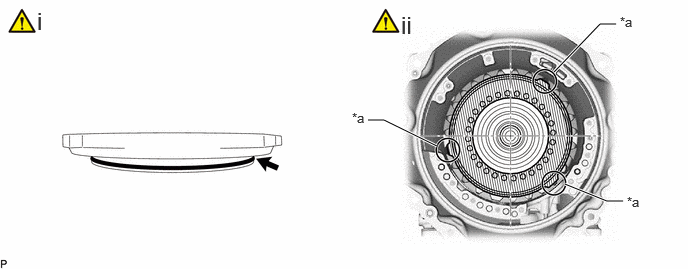
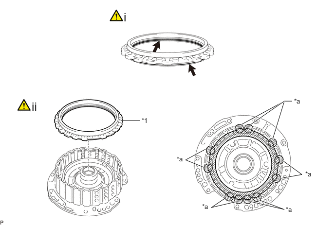
Hide 35639B 5.INSTALL BRAKE PLATE STOPPER SPRING
a.
C459077C01
2.25,0.427 2.417,0.427 2.417,0.427 2.417,0.51 true 3.479,2.667 3.844,2.698 3.844,2.698 4.042,2.698 true 0.375,0.052 0.656,0.406 0.281,0.354 18 false i 2.333,0.531 2.542,0.74 0.208,0.208 10 true *b 4.073,2.583 4.302,2.74 0.229,0.156 10 true *a
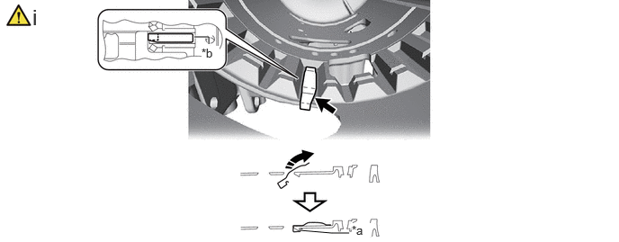
*a Securely install the case stopper *b Groove of automatic transmission case
V113147

Install in the direction of the arrow - -


i.

Install the brake plate stopper spring to the automatic transmission case sub-assembly as shown in the illustration.

NOTICE:

Install the brake plate stopper spring to the groove in the automatic transmission case sub-assembly and push until it is secured to the automatic transmission case stopper.


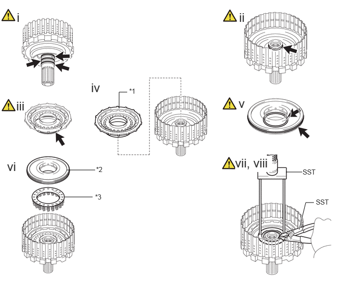
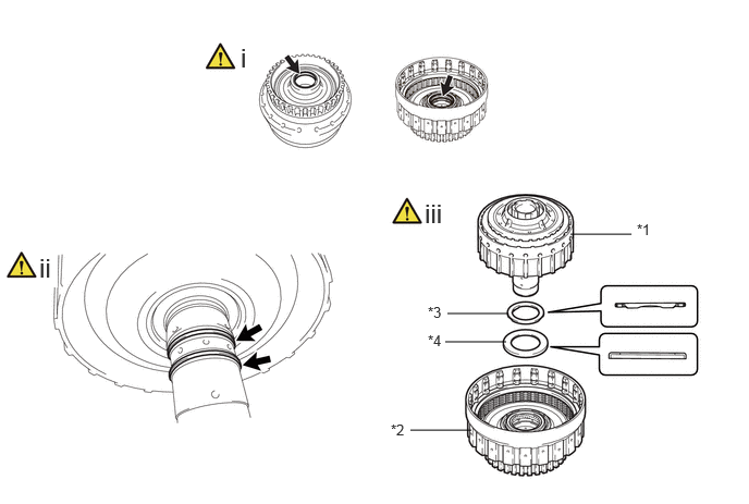
Hide 34638 6.INSTALL C-4 CLUTCH PISTON

a.
C459128C01
2.438,2.219 2.438,1.885 2.438,1.885 2.604,1.885 false 5.854,3.521 6.188,3.521 false 6.125,4.698 6.26,4.146 6.26,4.146 6.427,4.146 true 1.313,4.031 1.896,4.031 false 1.365,3.479 1.948,3.479 false 2.646,1.781 2.958,1.938 0.313,0.156 10 false *1 6.198,3.438 6.51,3.594 0.313,0.156 10 false SST 6.469,4.052 6.854,4.365 0.385,0.313 10 false SST 1.969,3.385 2.281,3.542 0.313,0.156 10 false *2 1.948,3.948 2.26,4.104 0.313,0.156 10 false *3 0.344,0.208 0.625,0.563 0.281,0.354 18 false i 4.896,0.208 5.177,0.563 0.281,0.354 18 false ii 0.333,2.021 0.615,2.375 0.281,0.354 18 false iii 1.865,1.646 2.146,2 0.281,0.354 18 false iv 4.885,1.969 5.167,2.323 0.281,0.354 18 false v 0.146,3.26 0.427,3.615 0.281,0.354 18 false vi 4.813,3.188 5.573,3.521 0.76,0.333 18 true vii, viii
*1 C-4 Clutch Piston *2 C-4 Clutch Balancer
*3 Forward Clutch Return Spring Sub-assembly (C-4 clutch) - -


i.

Coat 3 new clutch drum oil seal rings with ATF and install them to the output shaft assembly.


ii.

Coat a new O-ring with ATF and install it to the output shaft assembly.


iii.

Coat a new O-ring with ATF and install it to the C-4 clutch piston.


iv.

Install the C-4 clutch piston to the output shaft assembly.


v.

Coat 2 new O-rings with ATF and install them to the C-4 clutch balancer.


vi.

Install the C-4 clutch balancer and forward clutch return spring sub-assembly (C-4 clutch) to the output shaft assembly.


vii.

Set SST on the C-4 clutch balancer and compress the forward clutch return spring sub-assembly (C-4 clutch) using a press.

SST
09387-00020  

NOTICE:

Stop the press when the C-4 clutch balancer is lowered to a place 1 to 2 mm (0.0394 to 0.0787 in.) below the snap ring groove to prevent the forward clutch return spring sub-assembly (C-4 clutch) from being deformed.


viii.

Using SST, install the snap ring to the output shaft assembly.

SST
09350-30020  

NOTICE:
·

Make sure that the end gap of the snap ring is not aligned with a spring retainer claw.

·

Do not expand the snap ring excessively.


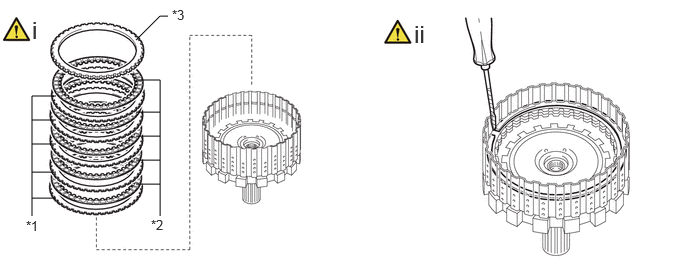
Hide 35883C 7.INSTALL NO. 4 CLUTCH DISC

a.
C459119C01
0.333,2.25 0.333,1 0.333,1 0.583,1 false 0.333,1.25 0.583,1.25 false 0.333,1.5 0.583,1.5 false 0.333,1.792 0.583,1.792 false 0.333,2.063 0.583,2.063 false 1.667,2.25 1.667,0.833 1.667,0.833 1.417,0.833 false 1.417,1.167 1.667,1.167 false 1.417,1.417 1.667,1.417 false 1.417,1.667 1.667,1.667 false 1.417,1.917 1.667,1.917 false 1.75,0.167 1.667,0.167 1.667,0.167 1.417,0.417 false 0.271,2.271 0.583,2.427 0.313,0.156 10 false *1 1.792,0.073 2.104,0.229 0.313,0.156 10 false *3 4.313,0.208 4.865,0.563 0.552,0.354 18 false ii 1.573,2.26 1.885,2.417 0.313,0.156 10 false *2 0.333,0.167 0.885,0.521 0.552,0.354 18 false i
*1 No. 4 Clutch Plate *2 No. 4 Clutch Disc
*3 Clutch Flange - -


i.

Install the 5 No. 4 clutch plates, 5 No. 4 clutch discs and clutch flange to the output shaft assembly.

NOTICE:

Make sure that the No. 4 clutch discs, No. 4 clutch plates and clutch flange are installed in the correct order.


ii.

Using a screwdriver, install the snap ring to the output shaft assembly.

NOTICE:

Be careful not to damage the output shaft assembly.


HINT:

Tape the screwdriver tip before use.


Hide 8.INSPECT PISTON STROKE OF NO. 4 CLUTCH

Z101186

(Click here)

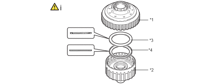
Hide 35650 9.INSTALL REAR MULTIPLE DISC CLUTCH ASSEMBLY
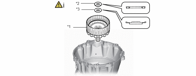
a.
C455648C01
2.677,1.01 3.177,1.01 false 2.958,0.125 3.458,0.125 false 2.979,0.354 3.479,0.354 true 2.458,0.896 2.771,1.052 0.313,0.156 10 false *1 2.771,0.042 3.083,0.198 0.313,0.156 10 false *2 2.781,0.25 3.094,0.406 0.313,0.156 10 false *3 2.302,0.042 2.583,0.396 0.281,0.354 18 false i
*1 Rear Multiple Disc Clutch Assembly *2 Thrust Needle Roller Bearing (I)
*3 Thrust Bearing Race (I) - -


i.

Install the rear multiple disc clutch assembly, thrust needle roller bearing and thrust bearing race to the automatic transmission case sub-assembly.

Thrust Needle Roller Bearing and Thrust Bearing Race Diameter:
Item Inside Outside
Thrust needle roller bearing (I) 30.00 mm (1.181 in.) 50.10 mm (1.972 in.)
Thrust bearing race (I) 31.83 mm (1.253 in.) 52.11 mm (2.052 in.)


Hide 35762 10.INSTALL REAR PLANETARY RING GEAR FLANGE
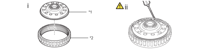
a.
C459141C01
2.448,0.438 3.115,0.438 false 2.51,1.385 3.177,1.385 false 3.188,0.354 3.5,0.51 0.313,0.156 10 false *1 3.229,1.302 3.542,1.458 0.313,0.156 10 false *2 0.979,0.052 1.26,0.406 0.281,0.354 18 false i 4.49,0.104 4.771,0.458 0.281,0.354 18 false ii
*1 Rear Planetary Ring Gear Flange *2 Rear Planetary Ring Gear


i.

Install the rear planetary ring gear flange to the rear planetary ring gear.


ii.

Using a screwdriver, install the snap ring to the rear planetary ring gear.

NOTICE:

Be careful not to damage the rear planetary ring gear.


HINT:

Tape the screwdriver tip before use.


Hide 35761 11.INSTALL REAR PLANETARY RING GEAR WITH REAR PLANETARY RING GEAR FLANGE
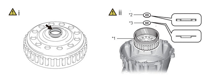
a.
C456978C01
4.031,1.333 4.615,1.333 false 4.604,0.51 4.938,0.51 false 4.615,0.792 4.948,0.792 false 3.854,1.24 4.104,1.479 0.25,0.24 10 false *1 4.438,0.427 4.75,0.583 0.313,0.156 10 false *2 4.448,0.708 4.76,0.865 0.313,0.156 10 false *3 0.625,0.292 1,0.771 0.375,0.479 18 false i 4.083,0.281 4.458,0.76 0.375,0.479 18 false ii
*1 Rear Planetary Ring Gear with Rear Planetary Ring Gear Flange *2 Thrust Needle Roller Bearing (H)
*3 Thrust Bearing Race (H) - -


i.

Coat the inside of the rear planetary ring gear with rear planetary ring gear flange with ATF.


ii.

Install the rear planetary ring gear with rear planetary ring gear flange, thrust needle roller bearing and thrust bearing race to the automatic transmission case sub-assembly.

Thrust Needle Roller Bearing and Thrust Bearing Race Diameter:
Item Inside Outside
Thrust needle roller bearing (H) 22.70 mm (0.894 in.) 48.40 mm (1.906 in.)
Thrust bearing race (H) 25.00 mm (0.984 in.) 48.40 mm (1.906 in.)


Hide 35706H 12.INSTALL PLANETARY SUN GEAR SUB-ASSEMBLY
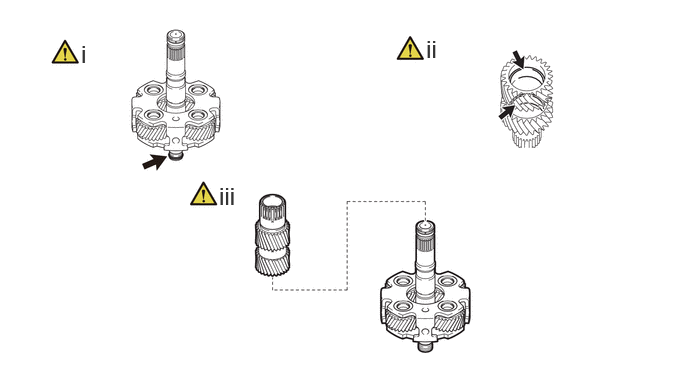
a.
C455657N01
0.844,0.417 1.125,0.771 0.281,0.354 18 false i 4.438,0.365 4.719,0.719 0.281,0.354 18 false ii 2.281,1.896 2.563,2.25 0.281,0.354 18 false iii

i.

Coat a new oil seal ring with ATF and install it to the rear planetary gear assembly.


ii.

Coat the inside of the planetary sun gear sub-assembly bushing with ATF.


iii.

Install the planetary sun gear sub-assembly to the rear planetary gear assembly.

NOTICE:

Check that the planetary sun gear sub-assembly rotates smoothly.


Hide 35750 13.INSTALL CENTER PLANETARY GEAR ASSEMBLY
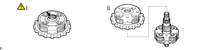
a.
C468576N01
0.927,0.125 1.219,0.531 0.292,0.406 18 false i 3.813,0.135 4.104,0.542 0.292,0.406 18 false ii

i.

Coat the inside of the center planetary gear assembly bearing with ATF.


ii.

Install the center planetary gear assembly to the rear planetary gear assembly.


Hide 35760 14.INSTALL REAR PLANETARY GEAR ASSEMBLY WITH PLANETARY SUN GEAR SUB-ASSEMBLY AND CENTER PLANETARY GEAR ASSEMBLY
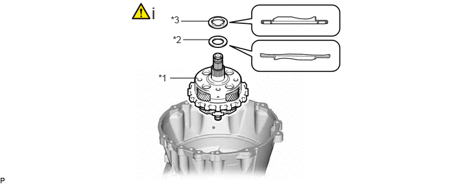
a.
C468577C01
2.583,1.188 3,1.188 false 2.75,0.323 3.167,0.323 false 2.781,0.604 3.198,0.604 false 2.406,1.104 2.729,1.406 0.323,0.302 10 false *1 2.625,0.521 2.938,0.677 0.313,0.156 10 false *2 2.594,0.219 2.906,0.375 0.313,0.156 10 false *3 2.302,0.052 2.479,0.438 0.177,0.385 18 false i
*1 Rear Planetary Gear Assembly with Planetary Sun Gear Sub-assembly and Center Planetary Gear Assembly *2 Thrust Bearing Race (G)
*3 Thrust Needle Roller Bearing (G) - -


i.

Install the rear planetary gear assembly with planetary sun gear sub-assembly and center planetary gear assembly, thrust needle roller bearing and thrust bearing race to the automatic transmission case sub-assembly.

Thrust Needle Roller Bearing and Thrust Bearing Race Diameter:
Item Inside Outside
Thrust needle roller bearing (G) 39.90 mm (1.571 in.) 64.50 mm (2.539 in.)
Thrust bearing race (G) 38.90 mm (1.531 in.) 68.20 mm (2.685 in.)


Hide 35769 15.INSTALL CENTER PLANETARY RING GEAR FLANGE
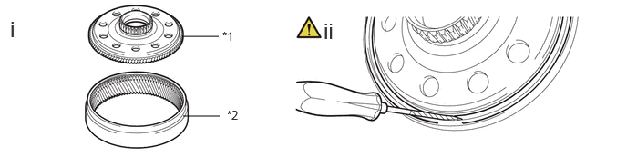
a.
C459132C01
2.083,0.417 2.5,0.417 false 2.094,1.333 2.51,1.333 false 0.115,0.188 0.375,0.521 0.26,0.333 18 true i 3.698,0.208 3.958,0.542 0.26,0.333 18 true ii 2.542,0.333 2.854,0.49 0.313,0.156 10 false *1 2.594,1.24 2.906,1.396 0.313,0.156 10 false *2
*1 Center Planetary Ring Gear Flange *2 Center Planetary Ring Gear


i.

Install the center planetary ring gear flange to the center planetary ring gear.


ii.

Using a screwdriver, install the snap ring to the center planetary ring gear.

NOTICE:

Be careful not to damage the rear planetary ring gear.


HINT:

Tape the screwdriver tip before use.


Hide 35763 16.INSTALL CENTER PLANETARY RING GEAR WITH CENTER PLANETARY RING GEAR FLANGE

Hide 35623S 17.INSTALL 1ST AND REVERSE BRAKE PISTON
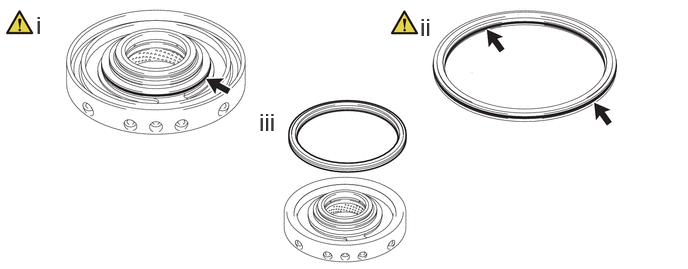
a.
C459133N01
0.375,0.115 0.656,0.469 0.281,0.354 18 false i 4.375,0.135 4.656,0.49 0.281,0.354 18 false ii 2.698,1.125 2.979,1.479 0.281,0.354 18 false iii

i.

Coat a new O-ring with ATF and install it to the center support assembly.


ii.

Coat 2 new O-rings with ATF and install them to the 1st and reverse brake piston.


iii.

Install the 1st and reverse brake piston to the center support assembly.


Hide 35620 18.INSTALL CENTER SUPPORT ASSEMBLY
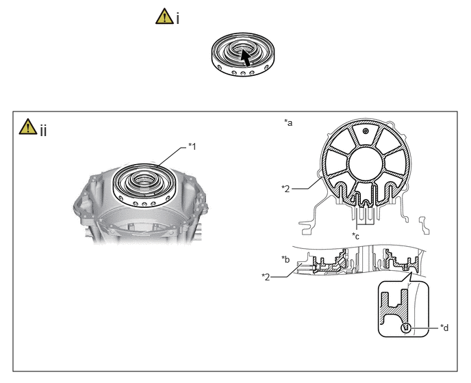
a.
C468566C01
0.198,1.698 6.958,5.656 6.76,3.958 2.375,2.552 2.75,2.25 2.75,2.25 2.833,2.25 false 5.438,3.417 5.688,3.417 5.688,3.417 5.688,3.167 false 5.563,3.417 5.563,3.167 false 5.427,3.5 5.427,3.167 false 6.25,5 6.667,5 true 4.438,2.875 4.688,2.875 4.688,2.875 4.906,2.688 false 4.115,4.219 4.365,4.219 4.365,4.219 4.594,4.01 true 0.604,1.833 1.156,2.188 0.552,0.354 18 false ii 2.677,0.125 3.229,0.479 0.552,0.354 18 false i 2.865,2.146 3.177,2.302 0.313,0.156 10 false *1 4.281,2.792 4.594,2.948 0.313,0.156 10 false *2 4.323,1.781 4.635,1.938 0.313,0.156 10 false *a 4.281,3.865 4.594,4.021 0.313,0.156 10 false *b 5.354,3.51 5.688,3.667 0.333,0.156 10 false *c 6.698,4.906 7.01,5.063 0.313,0.156 10 false *d 3.979,4.135 4.292,4.292 0.313,0.156 10 false *2
*1 Center Support Assembly *2 Automatic Transmission Case Sub-assembly
*a Top View *b Cross Sectional View
*c Oil Hole *d Automatic Transmission Case Sub-assembly Contact Surface


i.

Coat the inside of the center support assembly bushing with ATF.


ii.

Install the center support assembly to the automatic transmission case sub-assembly.

NOTICE:
·

Check that the oil holes of the center support assembly and automatic transmission case are aligned.

·

Install the bolt with the center support assembly the surface of the automatic transmission case sub-assembly.


Hide 35622G 19.INSTALL NO.2 BRAKE PISTON

a.
C468565C01
3.833,1.25 4,1.25 4,1.25 4.552,1.521 true 5.771,0.75 6.25,0.25 6.25,0.25 6.417,0.25 true 5.885,1.917 6.323,2.094 6.323,2.094 6.49,2.094 true 0.385,0.073 0.667,0.427 0.281,0.354 18 false i 4.177,0.115 4.458,0.469 0.281,0.354 18 false ii 3.667,1.146 3.979,1.302 0.313,0.156 10 false *a 6.458,0.146 6.771,0.302 0.313,0.156 10 false *a 6.531,2.021 6.844,2.177 0.313,0.156 10 false *a
*a Claw of No. 2 Brake Piston - -


i.

Coat a new O-ring with ATF and install it to the No. 2 brake piston.


ii.

Install the No. 2 brake piston to the automatic transmission case sub-assembly.

NOTICE:

Install so that the claw of the No. 2 brake piston is facing the position shown in the illustration.


Hide 35608A 20.INSTALL BRAKE PISTON RETURN SPRING SUB-ASSEMBLY
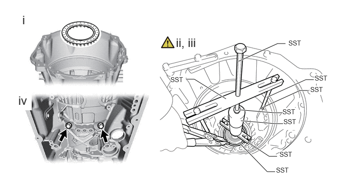
a.
C456934N01
5.01,1.292 5.833,0.917 5.833,0.917 6,0.917 true 3.917,1.667 4.083,1.667 4.083,1.667 4.75,2.083 true 5.604,2.052 6.427,1.677 6.427,1.677 6.594,1.677 true 5.479,2.281 6.302,1.906 6.302,1.906 6.469,1.906 true 5.042,2.313 5.76,2.375 5.76,2.375 5.927,2.375 true 5.063,2.542 5.781,2.604 5.781,2.604 5.948,2.604 true 5.198,2.99 5.656,3.292 5.656,3.292 5.823,3.292 true 5.021,3 5.615,3.615 5.615,3.615 5.781,3.615 true 0.469,0.271 0.75,0.625 0.281,0.354 18 false i 3.698,0.75 4.208,1.115 0.51,0.365 18 false ii, iii 0.385,1.969 0.667,2.323 0.281,0.354 18 true iv 6.063,0.823 6.521,1.021 0.458,0.198 10 false SST 6.615,1.563 7.073,1.76 0.458,0.198 10 true SST 6.521,1.802 6.979,2 0.458,0.198 10 true SST 3.583,1.594 3.906,1.854 0.323,0.26 10 true SST 5.802,3.5 6.125,3.76 0.323,0.26 10 true SST 5.875,3.167 6.198,3.427 0.323,0.26 10 true SST 5.938,2.271 6.26,2.531 0.323,0.26 10 true SST 5.958,2.479 6.281,2.74 0.323,0.26 10 true SST

i.

Install the brake piston return spring sub-assembly (No. 2 brake) to the No. 2 brake piston.


ii.

Set SST on the brake piston return spring sub-assembly (No. 2 brake) and automatic transmission case sub-assembly, and tighten SST to compress the brake piston return spring sub-assembly (No. 2 brake).

SST
09308-14010  
09380-60012  (09381-06010, 09381-06020, 09381-06040, 09381-06050, 09381-06090, 09381-06120, 09381-06140)


iii.

Using snap ring expander, install the hole snap ring to the center support assembly, 1st and reverse brake piston with No. 2 brake piston.


iv.

Install the 2 bolts to the center support assembly, 1st and reverse brake piston with No. 2 brake piston.

Torque:
25.5 N*m (260 kgf*cm, 19 ft.*lbf)


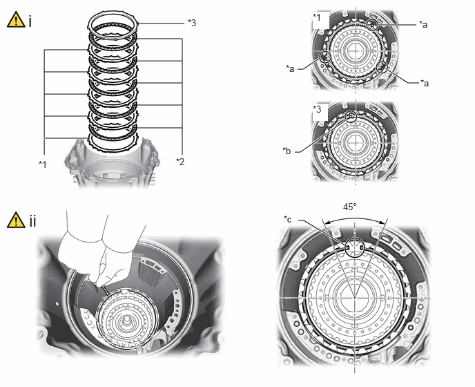
Hide 35682A 21.INSTALL NO. 2 BRAKE DISC

a.
C459092C01
0.667,2.333 0.667,0.75 0.667,0.75 1.333,0.75 false 0.667,1.417 1.333,1.417 false 0.667,1.083 1.333,1.083 false 0.667,1.75 1.333,1.75 false 0.667,2.083 1.333,2.083 true 2.75,2.333 2.75,0.583 2.75,0.583 2,0.583 false 2.021,0.917 2.75,0.917 false 2.031,1.25 2.75,1.25 false 2.031,1.583 2.75,1.583 false 2.042,1.927 2.75,1.927 false 2.052,0.354 2.781,0.354 false 6.323,1.25 6.156,1.25 6.156,1.25 5.813,1.031 true 4.823,0.875 4.573,1.042 4.573,1.042 4.49,1.042 true 5.698,0.375 6.281,0.375 true 5.229,1.802 4.531,2.292 4.531,2.292 4.448,2.292 true 5.208,3.698 4.583,3.323 4.583,3.323 4.5,3.323 true 0.583,2.396 0.896,2.552 0.313,0.156 10 false *1 2.656,2.354 2.969,2.51 0.313,0.156 10 false *2 2.833,0.26 3.146,0.417 0.313,0.156 10 false *3 6.323,0.281 6.635,0.438 0.313,0.156 10 false *a 6.344,1.167 6.656,1.323 0.313,0.156 10 false *a 4.313,0.948 4.625,1.104 0.313,0.156 10 false *a 4.719,1.563 4.948,1.823 0.229,0.26 10 true *3 4.719,0.177 4.969,0.438 0.25,0.26 10 true *1 4.26,2.188 4.573,2.344 0.313,0.156 10 false *b 5.177,3.031 5.635,3.229 0.458,0.198 10 false 45° 4.281,3.219 4.594,3.375 0.313,0.156 10 false *c 0.427,0.167 0.688,0.552 0.26,0.385 18 false i 0.438,3.177 0.698,3.563 0.26,0.385 18 false ii
*1 No. 2 Brake Plate *2 No. 2 Brake Disc
*3 No. 2 Brake Flange - -
*a Equal width claws of the No. 2 brake plate *b Mark
*c Snap ring end gap position - -


i.

Install the 5 No. 2 brake plates, 5 No. 2 brake discs and No. 2 brake flange to the automatic transmission case sub-assembly.

NOTICE:
·

Install so that the equal width claw of the No. 2 brake plate is facing the position shown in the illustration.

·

Install so that the mark of the No. 2 brake flange is facing the position shown in the illustration.

·

Make sure that the No. 2 brake discs and No. 2 brake plates, No. 2 brake flange are installed in the correct order.


ii.

Using a screwdriver, install the snap ring to the automatic transmission case sub-assembly.

NOTICE:
·

The snap ring end gap position must be within the 45° range shown in the illustration.

·

Be careful not to damage the automatic transmission case sub-assembly.


HINT:

Tape the screwdriver tip before use.


Hide 35682A 22.INSPECT PISTON STROKE OF NO. 2 BRAKE

Z101186

(Click here)

Hide 35640 23.INSTALL C-3 CLUTCH ASSEMBLY

Hide 35640 24.INSPECT PISTON STROKE OF NO. 3 CLUTCH

Z101186

(Click here)

Hide 35610 25.INSPECT PISTON STROKE OF C-1 CLUTCH ASSEMBLY

Z101186

(Click here)

Hide 35650L 26.INSTALL C-2 CLUTCH ASSEMBLY

a.
C459140C01
4.583,0.667 4.917,0.667 false 4.333,1.333 4.917,1.333 false 4.333,1.667 4.917,1.667 false 4.417,2.333 4.917,2.333 false 4.969,0.573 5.281,0.729 0.313,0.156 10 false *1 4.969,2.25 5.281,2.406 0.313,0.156 10 false *2 4.958,1.26 5.271,1.417 0.313,0.156 10 false *3 4.927,1.583 5.24,1.74 0.313,0.156 10 false *4 1.99,0.104 2.271,0.458 0.281,0.354 18 false i
*1 C-2 Clutch Assembly *2 C-2 Drum Sub-assembly
*3 Thrust Needle Roller Bearing (D) *4 Thrust Bearing Race (D)


i.

Install the C-2 clutch assembly, thrust needle roller bearing and thrust bearing race to the C-2 drum sub-assembly.

Thrust Needle Roller Bearing and Thrust Bearing Race Diameter:
Item Inside Outside
Thrust needle roller bearing (D) 47.60 mm (1.874 in.) 63.80 mm (2.512 in.)
Thrust bearing race (D) 49.60 mm (1.953 in.) 66.70 mm (2.626 in.)


Hide 3560B 27.INSTALL C-2 DRUM SUB-ASSEMBLY

Z101186

NOTICE:

Do not disassemble the C-1 clutch assembly.

If disassembled, replace the C-1 clutch assembly with a new one.


a.
C459088C01
4.26,3.271 4.844,3.271 false 4.281,3 4.865,3 false 5.458,2.24 6.042,2.24 false 3.927,4.115 4.51,4.115 false 2.302,0.406 2.583,0.76 0.281,0.354 18 false i 0.375,2.417 0.552,2.75 0.177,0.333 18 true ii 4.063,1.896 4.323,2.292 0.26,0.396 18 false iii 6.094,2.115 6.406,2.271 0.313,0.156 10 false *1 3.74,4.031 4.052,4.188 0.313,0.156 10 false *2 4.094,2.906 4.406,3.063 0.313,0.156 10 false *3 4.094,3.177 4.406,3.333 0.313,0.156 10 false *4
*1 C-2 Clutch Assembly with C-2 Drum Sub-assembly *2 C-1 Clutch Assembly
*3 Thrust Needle Roller Bearing (E) *4 Thrust Bearing Race (E)


i.

Coat the inside of the C-1 clutch assembly bushing with ATF.


ii.

Coat 2 new oil seal rings with ATF and install them to the C-2 drum sub-assembly.


iii.

Install the C-2 clutch assembly with C-2 drum sub-assembly, thrust needle roller bearing and thrust bearing race to the C-1 clutch assembly.

Thrust Needle Roller Bearing and Thrust Bearing Race Diameter:
Item Inside Outside
Thrust needle roller bearing (E) 50.60 mm (1.992 in.) 69.20 mm (2.724 in.)
Thrust bearing race (E) 54.20 mm (2.134 in.) 76.10 mm (2.996 in.)


Hide 35743 28.INSTALL FRONT PLANETARY RING GEAR
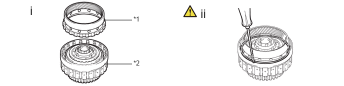
a.
C459149C01
2.167,0.417 2.75,0.417 false 2.167,1.333 2.75,1.333 false 0.625,0.073 0.906,0.427 0.281,0.354 18 false i 4.177,0.135 4.458,0.49 0.281,0.354 18 false ii 2.781,0.313 3.094,0.51 0.313,0.198 10 false *1 2.781,1.229 3.094,1.427 0.313,0.198 10 false *2
*1 Front Planetary Ring Gear *2 C-1 Clutch Assembly with C-2 Drum Sub-assembly


i.

Install the front planetary ring gear to the C-1 clutch assembly with C-2 drum sub-assembly.


ii.

Using a screwdriver, install the snap ring to the front planetary ring gear with C-1 clutch assembly.

NOTICE:

Be careful not to damage the front planetary ring gear with C-1 clutch assembly.


HINT:

Tape the screwdriver tip before use.


Hide 35743 29.INSTALL FRONT PLANETARY RING GEAR WITH C-1 CLUTCH ASSEMBLY
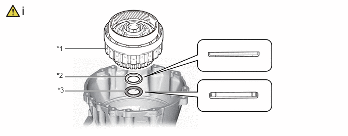
a.
C459089C01
1.333,1 2.167,1 false 1.333,1.583 2.583,1.583 true 1.344,1.875 2.594,1.875 true 1.167,0.917 1.5,1.167 0.333,0.25 10 false *1 1.167,1.469 1.479,1.656 0.313,0.188 10 false *2 1.188,1.771 1.5,1.927 0.313,0.156 10 false *3 0.448,0.073 0.729,0.427 0.281,0.354 18 false i
*1 Front Planetary Ring Gear with C-1 Clutch Assembly *2 Thrust Bearing Race (F)
*3 Thrust Needle Roller Bearing (F) - -


i.

Install the front planetary ring gear with C-1 clutch assembly and thrust needle roller bearing, thrust bearing race.

Thrust Needle Roller Bearing and Thrust Bearing Race Diameter:
Item Inside Outside
Thrust bearing race (F) 45.90 mm (1.807 in.) 63.35 mm (2.494 in.)
Thrust needle roller bearing (F) 45.90 mm (1.807 in.) 62.10 mm (2.445 in.)


Hide 3560B 30.INSPECT PISTON STROKE OF C-2 CLUTCH ASSEMBLY

Z101186

(Click here)

Hide 35753B 31.INSTALL FRONT PLANETARY OIL RECEIVER

Hide 35706P 32.INSTALL FRONT PLANETARY SUN GEAR SUB-ASSEMBLY
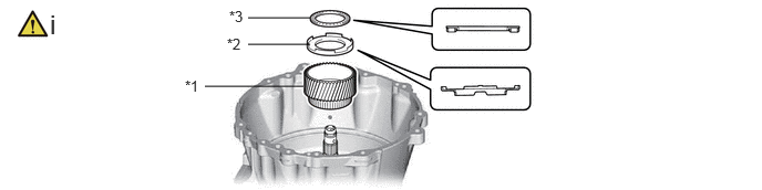
a.
C459083C01
2.333,0.167 2.917,0.167 false 2.333,0.417 2.917,0.417 false 1.927,0.813 2.854,0.813 false 2.156,0.073 2.469,0.229 0.313,0.156 10 false *3 0.469,0.083 0.75,0.438 0.281,0.354 18 false i 1.74,0.729 2.052,0.885 0.313,0.156 10 false *1 2.135,0.333 2.448,0.49 0.313,0.156 10 false *2
*1 Front Planetary Sun Gear Sub-assembly *2 Thrust Bearing Race (C)
*3 Thrust Needle Roller Bearing (C) - -


i.

Install the front planetary sun gear sub-assembly and thrust needle roller bearing, thrust bearing race.

Thrust Needle Roller Bearing and Thrust Bearing Race Diameter:
Item Inside Outside
Thrust needle roller bearing (C) 37.50 mm (1.476 in.) 55.80 mm (2.197 in.)
Thrust bearing race (C) 38.20 mm (1.504 in.) 59.67 mm (2.349 in.)


Hide 35710G 33.INSTALL PLANETARY SUN GEAR ASSEMBLY
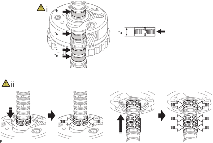
a.
C459143C01
3.979,1.01 4.292,1.208 0.313,0.198 10 false *a 1.552,0.156 1.833,0.51 0.281,0.354 18 false i 0.365,2.688 0.646,3.042 0.281,0.354 18 false ii 1.833,0.281 2.083,0.51 0.25,0.229 10 true *b 1.833,1.042 2.083,1.271 0.25,0.229 10 true *c 1.823,1.542 2.073,1.771 0.25,0.229 10 true *c 1.833,1.792 2.083,2.021 0.25,0.229 10 true *c
*a Width *b for Upper Side
*c for Lower Side - -
V113147

Install in this direction
V113148

Close the opening of the bearing


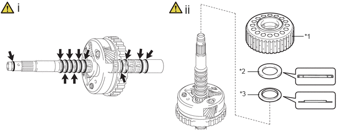
i.

for Upper Side

1. Coat the needle roller bearing and front planetary gear assembly with ATF.

NOTICE:

The bearing width is 14.4 mm (0.567 in.)


for Lower Side

1. Coat 3 needle roller bearings and front planetary gear assembly with ATF.

NOTICE:

The bearing width is 15.4 mm (0.606 in.)


ii.

Install the 4 needle roller bearings to the front planetary gear assembly as shown in the illustration.


b.
C459079C01
5.25,1.521 5.5,1.521 false 5.25,2.01 5.5,2.01 false 6.188,0.771 6.438,0.771 false 5.083,1.906 5.396,2.104 0.313,0.198 10 false *3 0.365,0.01 0.646,0.365 0.281,0.354 18 false i 6.458,0.688 6.771,0.885 0.313,0.198 10 false *1 5.073,1.427 5.385,1.625 0.313,0.198 10 false *2 3.917,0.052 4.198,0.406 0.281,0.354 18 false ii
*1 Planetary Sun Gear Assembly *2 Thrust Needle Roller Bearing (B)
*3 Thrust Bearing Race (B) - -


i.

Coat 11 new oil seal rings with ATF and install them to the front planetary gear assembly.


ii.

Install the planetary sun gear assembly, thrust needle roller bearing and thrust bearing race to the front planetary gear assembly.

Thrust Needle Roller Bearing and Thrust Bearing Race Diameter:
Item Inside Outside
Thrust needle roller bearing (B) 38.30 mm (1.508 in.) 58.10 mm (2.287 in.)
Thrust bearing race (B) 34.70 mm (1.366 in.) 55.00 mm (2.165 in.)


Hide 35720 34.INSTALL FRONT PLANETARY GEAR ASSEMBLY
a.
C459100C01
6.177,0.771 6.406,0.531 6.406,0.531 6.583,0.531 false 6.188,1.25 6.51,1.479 6.51,1.479 6.698,1.479 true 2.146,0.865 2.375,0.625 2.375,0.625 2.552,0.625 true 0.167,0.135 0.375,0.521 0.208,0.385 18 false i 4.094,0.104 4.302,0.49 0.208,0.385 18 false ii 6.625,0.427 6.875,0.646 0.25,0.219 10 false *1 6.74,1.375 6.969,1.583 0.229,0.208 10 false *2 6.49,0.958 6.708,1.198 0.219,0.24 10 false *a 2.604,0.51 2.854,0.729 0.25,0.219 10 true *1
*1 Front Planetary Gear Assembly *2 Front Planetary Ring Gear
*a Clearance - -


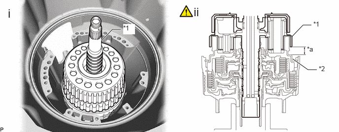
i.

Install the front planetary gear assembly to the front planetary ring gear with C-1 clutch assembly.


ii.

Measure the clearance between the front planetary gear assembly and front planetary ring gear and check that the measured value is within the specified range.

Standard Clearance:

15.7 to 17.6 mm (0.619 to 0.692 in.)


If the clearance is not as specified, check the installation condition of the gear train.


Hide 35621 35.INSTALL NO. 1 BRAKE PISTON

a.
C459154C01
5.167,2.667 6.083,2.167 6.083,2.167 6.25,2.167 true 6,3.823 6.458,3.74 6.458,3.74 6.042,3.438 true 5.833,2.979 6.083,2.167 true 5.365,2.667 6.083,2.167 true 5.375,4.323 6.083,4.49 6.083,4.49 5.531,4.281 true 5.052,4.323 4.521,4.448 4.521,4.448 4.813,4.25 true 4.354,3.583 3.969,3.427 3.969,3.427 4.396,3.198 true 2.583,2.583 3,2.583 false 2.646,0.219 2.927,0.573 0.281,0.354 18 false i 0.677,2.135 0.958,2.49 0.281,0.354 18 false ii 6.292,2.083 6.604,2.281 0.313,0.198 10 false *a 6.531,3.646 6.844,3.844 0.313,0.198 10 false *a 3.781,3.323 4.094,3.521 0.313,0.198 10 false *a 6.115,4.406 6.427,4.604 0.313,0.198 10 false *a 4.323,4.344 4.635,4.542 0.313,0.198 10 false *a 3.031,2.5 3.344,2.698 0.313,0.198 10 false *1
*1 No. 1 Brake Piston - -
*a Claw of No. 1 Brake Piston - -


i.

Coat 2 new O-rings with ATF and install them to the No. 1 brake piston.


ii.

Install the No. 1 brake piston to the front support sub-assembly.

NOTICE:

Install so that the claw of the No. 1 brake piston is facing the position shown in the illustration.


Hide 35608J 36.INSTALL BRAKE PISTON RETURN SPRING SUB-ASSEMBLY (NO. 1 BRAKE)
a.
C459124N01
5.917,0.552 6.333,0.552 false 5.75,0.833 6.333,0.833 false 5.635,1.052 6.063,1.167 6.063,1.167 6.344,1.167 true 5.635,1.219 6.115,1.427 6.115,1.427 6.396,1.427 true 4.406,1.479 4.573,1.479 4.573,1.479 5.115,1.01 true 0.771,0.094 1.052,0.448 0.281,0.354 18 false i 3.948,0.094 4.552,0.448 0.604,0.354 18 false ii, iii 6.396,0.458 6.854,0.656 0.458,0.198 10 false SST 6.365,0.74 6.823,0.938 0.458,0.198 10 false SST 6.375,1.042 6.833,1.24 0.458,0.198 10 false SST 6.438,1.313 6.896,1.51 0.458,0.198 10 false SST 4.115,1.396 4.573,1.594 0.458,0.198 10 false SST

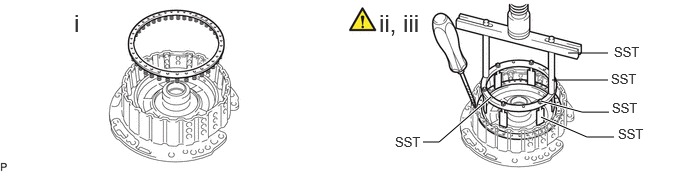
i.

Install the brake piston return spring sub-assembly (No. 1 brake) to the front support sub-assembly.


ii.

Set SST on the brake piston return spring sub-assembly (No. 1 brake), and compress the brake piston return spring sub-assembly (No. 1 brake) using a press.

SST
09380-60012  (09381-06010, 09381-06110, 09381-06100, 09381-06050)
09381-06160  


iii.

Using a screwdriver with its tip wrapped with protective tape, install the snap ring to the front support sub-assembly.

NOTICE:

Be careful not to damage the front support sub-assembly.


Hide 35681A 37.INSTALL NO. 1 BRAKE DISC

a.
C459146C01
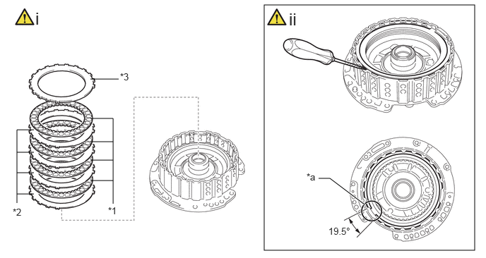
3.896,0.073 7,3.698 3.104,3.625 4.698,2.635 4.865,2.635 4.865,2.635 5.375,3.021 true 1.333,1.167 1.75,1.167 false 1.333,1.75 1.667,1.75 1.667,1.75 1.667,3.01 false 1.333,2.094 1.667,2.094 false 1.333,2.365 1.667,2.365 false 1.333,2.667 1.667,2.667 false 0.5,1.917 0.25,1.917 0.25,1.917 0.25,3 false 0.25,2.25 0.5,2.25 false 0.25,2.865 0.5,2.865 false 0.25,2.552 0.5,2.552 false 4.844,3.333 5.615,3.531 0.771,0.198 10 false 19.5° 0.521,0.125 0.844,0.49 0.323,0.365 18 false i 4.26,0.135 4.583,0.5 0.323,0.365 18 false ii 1.771,1.052 2.094,1.302 0.323,0.25 10 false *3 0.188,3.052 0.5,3.208 0.313,0.156 10 false *2 4.521,2.531 4.865,2.781 0.344,0.25 10 false *a 1.594,3.031 1.917,3.281 0.323,0.25 10 false *1
*1 No. 1 Brake Disc *2 No. 1 Brake Plate
*3 No. 1 Brake Flange - -
*a Snap Ring End Gap Position - -


i.

Install the 4 No. 1 brake plates and 4 No. 1 brake discs, No. 1 brake flange to the front support sub-assembly.

NOTICE:

Make sure that the No. 1 brake discs, No. 1 brake plates and No. 1 brake flange are installed in the correct order.


ii.

Using a screwdriver, install the snap ring to the front support sub-assembly.

NOTICE:
·

The snap ring end gap position must be within the angle shown in the illustration.

·

Make sure that both ends of the snap ring are fitted into the groove.

·

Be careful not to damage the front support sub-assembly.


HINT:

Tape the screwdriver tip before use.


Hide 35681A 38.INSPECT PISTON STROKE OF NO. 1 BRAKE

Z101186

(Click here)

Hide 35370 39.INSTALL STATOR SHAFT ASSEMBLY
a.
C459155C01
3.667,0.833 4.583,0.833 false 3.667,1.115 4.583,1.115 true 3.521,0.74 3.833,0.896 0.313,0.156 10 false *1 3.521,1.01 3.833,1.167 0.313,0.156 10 false *2 0.573,0.146 0.854,0.5 0.281,0.354 18 false i 4.021,0.177 4.302,0.531 0.281,0.354 18 false ii 0.448,2.625 0.729,2.979 0.281,0.354 18 false iii 4.26,2.635 4.542,2.99 0.281,0.354 18 false iv 1.698,1.729 2.01,1.885 0.313,0.156 10 false *a
*1 Thrust Bearing Race (A) *2 Thrust Needle Roller Bearing (A)
*a Clearance - -


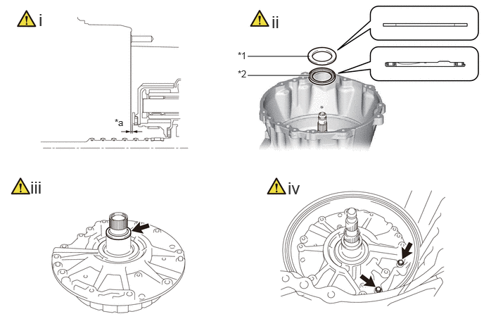
i.

Measure the distance between the end of the automatic transmission case sub-assembly and thrust bearing race.

Standard clearance:

1.02 to 1.85 mm (0.0402 to 0.0728 in.)


If the clearance is not as specified, replace the thrust bearing race with one of a different thickness. Use the table below to select a thrust bearing race which will ensure that the clearance is within the specification.

Thrust Bearing Race Thickness:
Part No. Thickness mm (in.)
35786-60020 2.46 to 2.54 mm (0.0969 to 0.0999 in.)
35786-60030 2.86 to 2.94 mm (0.1127 to 0.1157 in.)


ii.

Install the thrust needle roller bearing and thrust bearing race to the automatic transmission case sub-assembly.

Thrust Needle Roller Bearing and Thrust Bearing Race Diameter:
Item Inside Outside
Thrust bearing race (A) 67.10 mm (2.642 in.) 92.60 mm (3.646 in.)
Thrust needle roller bearing (A) 63.50 mm (2.500 in.) 84.70 mm (3.335 in.)


HINT:

Align the knock pin on the front oil pump assembly with the knock pin hole on the automatic transmission case sub-assembly.


iii.

Coat a new oil seal ring with ATF and install it to the stator shaft assembly.


iv.

Using a T50 "TORX" socket wrench, install the stator shaft assembly to the automatic transmission case sub-assembly with the 2 screws.

Torque:
18 N*m (184 kgf*cm, 13 ft.*lbf)


Hide 40.INSTALL OIL PUMP ASSEMBLY WITH DRIVEN SPROCKET

Torque:
18 N*m (184 kgf*cm, 13 ft.*lbf)

Hide 41.INSTALL DRIVE SPROCKET AND TRANSMISSION DRIVE CHAIN
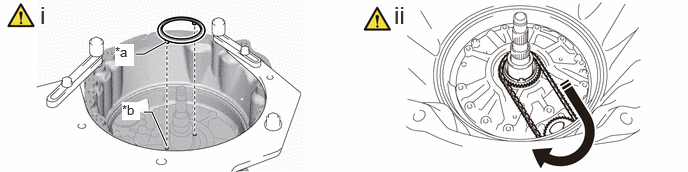
a.
C459127C01
1.5,1.167 1.583,1.167 1.583,1.167 1.74,1.521 true 1.417,0.563 1.5,0.563 1.5,0.563 1.729,0.438 true 1.198,0.458 1.396,0.688 0.198,0.229 10 true *a 1.271,1.063 1.458,1.25 0.188,0.188 10 true *b 0.417,0.01 0.698,0.365 0.281,0.354 18 false i 4.104,0.01 4.385,0.365 0.281,0.354 18 false ii
*a Protrusion *b Groove
V113147

Install While rotating - -


i.

Align the protrusion of the gear thrust washer with the groove of the stator shaft assembly, and install the gear thrust washer to the stator shaft assembly.


ii.

While rotating the transmission drive chain, install the drive sprocket and transmission drive chain.


Hide 35308K 42.INSTALL NO. 2 FRONT OIL PUMP COVER SUB-ASSEMBLY
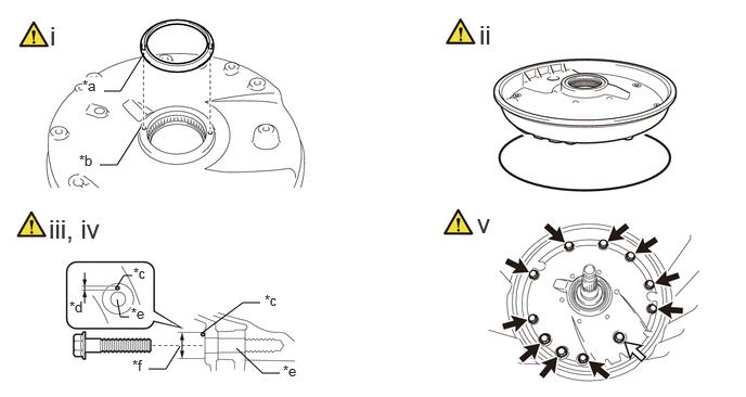
a.
C458272C02
2.271,3.344 2.521,3.583 2.521,3.583 2.688,3.583 false 1.125,2.875 1.156,3.042 1.156,3.042 1.24,3.042 false 0.99,0.875 1.156,0.875 1.156,0.875 1.385,0.51 false 0.958,1.583 1.125,1.583 1.125,1.583 1.354,1.219 true 1.125,2.75 1.188,2.646 1.188,2.646 1.271,2.646 false 1.938,3.198 2.333,2.906 2.333,2.906 2.5,2.906 false 1.427,3.542 1.594,3.542 1.594,3.542 1.729,3.323 false 0.479,0.198 0.635,0.552 0.156,0.354 18 false i 0.469,2.052 1.052,2.406 0.583,0.354 18 false iii, iv 1.26,2.927 1.438,3.115 0.177,0.188 10 true *e 1.281,2.542 1.469,2.729 0.188,0.188 10 false *c 0.667,2.865 0.906,3.083 0.24,0.219 10 false *d 0.792,0.74 1,0.969 0.208,0.229 10 true *a 2.719,3.479 2.99,3.656 0.271,0.177 10 false *e 0.76,1.458 0.938,1.688 0.177,0.229 10 true *b 2.542,2.802 2.729,2.99 0.188,0.188 10 false *c 1.271,3.427 1.51,3.646 0.24,0.219 10 false *f 4.604,0.188 4.854,0.542 0.25,0.354 18 false ii 4.583,2 4.875,2.292 0.292,0.292 18 false v
*a Protrusion *b Groove
*c Seal Packing *d Seal Diameter
*e Bolt Hole *f 12.0 to 15.0 mm (0.473 to 0.590 in.)
V100135

Bolt A
V100136

Bolt B


i.

Align the protrusion of the gear thrust washer with the groove of the No. 2 front oil pump cover sub-assembly, and install the gear thrust washer to the No. 2 front oil pump cover sub-assembly.


ii.

Coat a new O-ring with ATF and install it to the No. 2 front oil pump cover sub-assembly.


iii.

Clean the bolts and bolt installation seats of the No. 2 front oil pump cover sub-assembly with solvent.


iv.

Apply seal packing to the No. 2 front oil pump cover sub-assembly to the seating surface of each bolt as shown in the illustration.

Seal Packing:

Toyota Genuine Seal Packing 1281, Three Bond 1281 or equivalent


Standard Seal Diameter:

3.0 mm (0.118 in.) or more


NOTICE:
·

Do not apply seal packing inside the bolt hole.

·

Do not apply seal packing to the threaded portion of the bolt.


v.

Install the No. 2 front oil pump cover sub-assembly with the 11 bolts.

Torque:
for bolt A : 22 N*m (224 kgf*cm, 16 ft.*lbf)
for bolt B : 18 N*m (184 kgf*cm, 13 ft.*lbf)

Bolt Length:
Bolt A 42 mm (1.65 in.)
Bolt B 20 mm (0.787 in.)


HINT:

Align the knock pin on the stator shaft assembly with the knock pin hole of the No. 2 front oil pump cover sub-assembly.


Hide 43.INSPECT INPUT SHAFT END PLAY

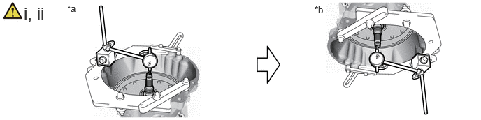
a.
C459099C01
0.354,0.052 0.917,0.417 0.563,0.365 18 false i, ii 1,0.042 1.313,0.198 0.313,0.156 10 false *a 4.688,0.063 5,0.219 0.313,0.156 10 false *b
*a Input shaft facing upwards *b Input shaft facing downwards


i.

With the input shaft facing upwards, set the dial gauge to 0 mm (0 in.).


ii.

Set the input shaft facing downwards and measure the amount of movement of the input shaft.

Standard End Play:

0.47 to 1.31 mm (0.0186 to 0.0515 in.)


If the end play is not as specified, check the installation condition inside the unit.


Hide 44.INSPECT INDIVIDUAL PISTON OPERATION

Z101186

Click here(Click here)

Hide 35505 45.INSTALL MANUAL VALVE LEVER SUB-ASSEMBLY
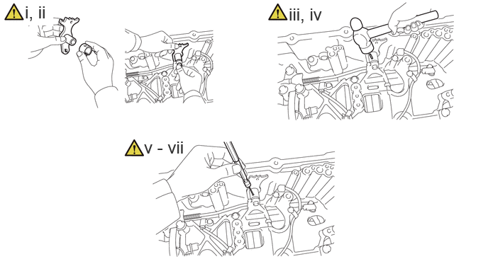
a.
C459096N01
0.365,0.031 0.781,0.375 0.417,0.344 18 true i, ii 4.24,0.063 4.813,0.406 0.573,0.344 18 false iii, iv 2.115,2.021 2.927,2.396 0.813,0.375 18 false v - vii

i.

Install a new spacer to the manual valve lever sub-assembly.


ii.

Install the manual valve lever shaft to the automatic transmission case sub-assembly through the manual valve lever sub-assembly.


iii.

Using a hammer, drive in a new spring pin.


iv.

Turn the spacer and manual valve lever shaft to align the smaller hole on the spacer with the indent on the manual valve lever sub-assembly.


v.

Using a 5 mm pin punch and a hammer, stake the spacer.


vi.

Check that the spacer does not turn.


vii.

Make sure that the manual valve lever shaft rotates smoothly.


Hide 35556 46.INSTALL PARKING LOCK PAWL SHAFT

Hide 35501 47.INSTALL PARKING LOCK ROD SUB-ASSEMBLY

Hide 35595 48.INSTALL PARKING LOCK PAWL BRACKET
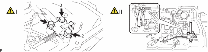
a.
C459097N01
0.531,0.24 0.813,0.594 0.281,0.354 18 false i 4.104,0.24 4.385,0.594 0.281,0.354 18 false ii 1.167,0.531 1.323,0.729 0.156,0.198 10 true 1 2.813,1.156 2.969,1.354 0.156,0.198 10 true 2 2.063,0.094 2.219,0.292 0.156,0.198 10 true 3

i.

Install the parking lock pawl bracket to the automatic transmission case sub-assembly with the 3 bolts, in several steps in the order shown in the illustration.

Torque:
48.4 N*m (494 kgf*cm, 36 ft.*lbf)


ii.

Move the manual valve lever sub-assembly to P, and check that the output shaft is locked by the parking lock pawl.


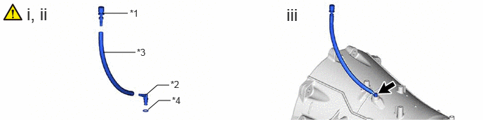
Hide 33129F 49.INSTALL TRANSMISSION OIL PIPE
a.
C458271N01
0.844,0.135 1.021,0.438 0.177,0.302 18 false i 3.646,0.146 3.854,0.49 0.208,0.344 18 false ii

i.

Coat 2 new O-rings with ATF and install them to the transmission oil pipe.


ii.

Install the transmission oil pipe to the oil pump assembly with driven sprocket.


Hide 82125J 50.INSTALL TRANSMISSION WIRE

Z101186

(Click here)

Hide 89413N 51.INSTALL TRANSMISSION REVOLUTION SENSOR (NT)

Hide 89413V 52.INSTALL TRANSMISSION REVOLUTION SENSOR (SP2)

Hide 35400A 53.INSTALL TRANSMISSION VALVE BODY ASSEMBLY

Z101186

(Click here)

Hide 35300D 54.INSTALL OIL PUMP WITH MOTOR ASSEMBLY (w/ Stop And Start System)
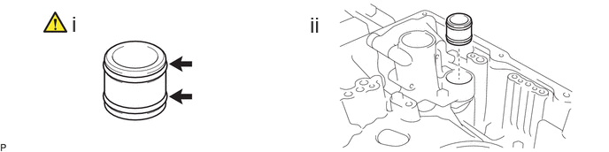
a.
C456965N01
1.969,1 2.406,1.344 2.406,1.344 2.24,1 true 0.427,0.063 0.813,0.458 0.385,0.396 18 false i, ii 3.823,0.042 4.208,0.438 0.385,0.396 18 false iii 2.458,1.302 2.917,1.5 0.458,0.198 10 false SST

i.

Using SST and a hammer, install a new oil seal to the automatic transmission case sub-assembly.

SST
09950-60011  (09951-00510)
09950-70010  (09951-07100)


ii.

Coat the lip of the oil seal with ATF.


iii.

Install the oil pump with motor assembly to the automatic transmission case sub-assembly with the 3 bolts.

Torque:
19.5 N*m (199 kgf*cm, 14 ft.*lbf)


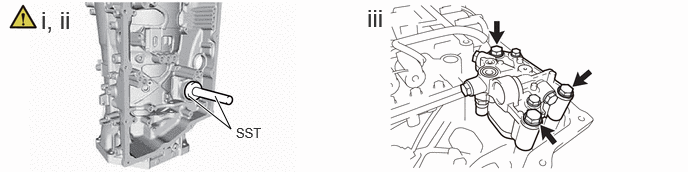
Hide 33129H 55.INSTALL NO. 3 TRANSMISSION OIL PIPE (w/ Stop And Start System)
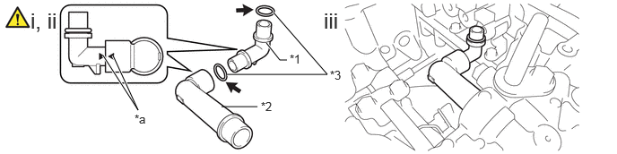
a.
C459148C01
1.198,0.646 1.604,1.281 1.604,1.281 1.313,0.646 true 2.635,0.865 3.802,0.865 3.802,0.865 3.177,0.146 true 3.094,0.5 3.25,0.698 3.25,0.698 3.333,0.698 true 2.573,1.24 2.99,1.24 false 0.354,0.094 0.833,0.406 0.479,0.313 18 false i, ii 3.76,0.094 4.24,0.406 0.479,0.313 18 false iii 1.563,1.302 1.875,1.5 0.313,0.198 10 false *a 3.833,0.792 4.146,0.99 0.313,0.198 10 false *3 3.365,0.604 3.677,0.802 0.313,0.198 10 false *1 3.031,1.156 3.344,1.354 0.313,0.198 10 false *2
*1 No. 3 Transmission Oil Pipe *2 No. 4 Transmission Oil Pipe
*3 O-ring - -
*a Matchmark - -


i.

Coat 2 new O-rings with ATF and install them to the No. 3 transmission oil pipe.


ii.

Align the matchmark and install the No. 3 transmission oil pipe to the No. 4 transmission oil pipe.


iii.

Install the No. 3 transmission oil pipe and No. 4 transmission oil pipe to the oil pump with motor assembly.


Hide 33129G 56.INSTALL NO. 2 TRANSMISSION OIL PIPE (w/ Stop And Start System)
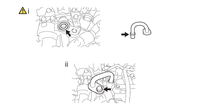
a.
C459157N01
0.958,0.229 1.24,0.583 0.281,0.354 18 false i 2.25,2.073 2.531,2.427 0.281,0.354 18 false ii

i.

Coat 2 new O-rings with ATF and install them to the No. 2 transmission oil pipe and oil pump with motor assembly.


ii.

Install the No. 2 transmission oil pipe with the bolt.

Torque:
9.5 N*m (97 kgf*cm, 84 in.*lbf)


Hide 35330 57.INSTALL VALVE BODY OIL STRAINER ASSEMBLY

Z101186

Click here(Click here)

Hide 35106 58.INSTALL AUTOMATIC TRANSMISSION OIL PAN SUB-ASSEMBLY
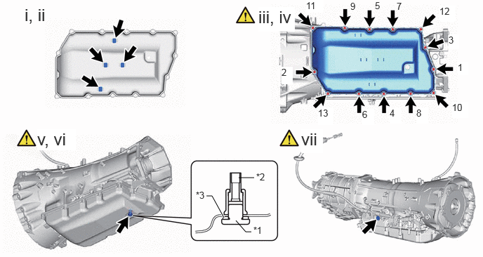
a.
C459162C01
3.542,2.635 3.771,2.635 false 3.063,2.906 3.146,2.906 3.146,2.906 3.323,3.229 true 3.5,3.271 3.646,3.438 3.646,3.438 3.729,3.438 false 3.76,3.333 4.073,3.49 0.313,0.156 10 false *1 3.802,2.542 4.115,2.698 0.313,0.156 10 false *2 2.906,2.813 3.219,2.969 0.313,0.156 10 false *3 0.365,0.073 0.813,0.458 0.448,0.385 18 false i, ii 3.833,0.104 4.375,0.469 0.542,0.365 18 true iii, iv 0.552,1.917 1.125,2.229 0.573,0.313 18 true v, vi 6.792,0.917 6.948,1.115 0.156,0.198 10 true 1 6.656,0.51 6.813,0.729 0.156,0.219 10 true 3 6.521,0.083 6.76,0.323 0.24,0.24 10 true 12 6.708,1.51 6.948,1.75 0.24,0.24 10 true 10 6.177,1.594 6.354,1.833 0.177,0.24 10 true 8 5.781,1.594 5.958,1.833 0.177,0.24 10 true 4 5.375,1.615 5.552,1.854 0.177,0.24 10 true 6 4.719,1.594 4.948,1.854 0.229,0.26 10 true 13 4.177,0.99 4.344,1.25 0.167,0.26 10 true 2 4.542,0 4.802,0.188 0.26,0.188 10 true 11 5.198,0.01 5.438,0.25 0.24,0.24 10 false 9 5.563,0 5.802,0.24 0.24,0.24 10 false 5 5.885,0.01 6.125,0.25 0.24,0.24 10 false 7 4.469,1.917 4.792,2.271 0.323,0.354 18 true vii
*1 Overflow Plug *2 No. 1 Transmission Oil Filler Tube
*3 Gasket - -


i.

Install the 4 transmission oil cleaner magnets to the automatic transmission oil pan sub-assembly.


ii.

Install a new automatic transmission oil pan gasket to the automatic transmission oil pan sub-assembly.


iii.

Temporarily install the automatic transmission oil pan sub-assembly to the automatic transmission case sub-assembly with the 13 bolts.


iv.

Tighten the 13 bolts in the order shown in the illustration.

Torque:
8.9 N*m (91 kgf*cm, 79 in.*lbf)


v.

Using a 6 mm hexagon socket wrench, install the No. 1 transmission oil filler tube to the automatic transmission case sub-assembly.

Torque:
1.7 N*m (17 kgf*cm, 15 in.*lbf)


vi.

Temporarily install the gasket and overflow plug to the automatic transmission assembly.

HINT:

Gasket replacement and tightening of the overflow plug are performed after the automatic transmission fluid level is adjusted.


vii.

Temporarily install the gasket and refill plug to the automatic transmission case sub-assembly.

HINT:

Gasket replacement and tightening of the refill plug are performed after the automatic transmission fluid level is adjusted.


Hide 84540 59.INSTALL PARK/NEUTRAL POSITION SWITCH ASSEMBLY

Z101186

HINT:

Make sure that the manual valve lever shaft has not been rotated prior to installing the park/neutral position switch assembly as the detent spring may become detached from the manual valve lever shaft.


a.
C459159C01
4.344,2.844 4.844,2.844 true 4.615,3.521 4.781,3.521 4.781,3.521 5.031,2.99 true 6.333,2.448 6.573,2.625 6.573,2.625 6.406,2.375 true 0.344,0.125 1.229,0.646 0.885,0.521 18 false i, ii 4.01,0.115 4.625,0.458 0.615,0.344 18 true iii, iv 0.344,1.969 1.021,2.323 0.677,0.354 18 true v - vii 4.021,1.969 4.74,2.281 0.719,0.313 18 true viii - x 4.125,2.729 4.344,2.938 0.219,0.208 10 true *a 4.427,3.417 4.656,3.604 0.229,0.188 10 true *b 3.896,3.948 4.146,4.313 0.25,0.365 18 true xii 1.344,1.896 1.5,2.094 0.156,0.198 10 true N 0.333,3.948 0.552,4.292 0.219,0.344 18 true xi 6.542,2.656 6.76,2.885 0.219,0.229 10 true *c
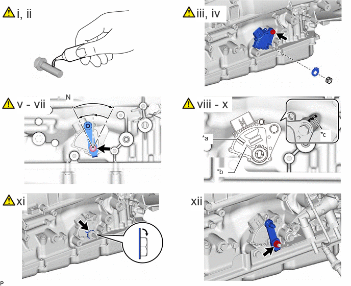
*a Neutral Basic Line *b Guide Pointer
*c Matchmark - -


i.

Clean the bolt and bolt hole.


ii.

Apply adhesive to 2 or 3 threads on the end of the bolt.

Adhesive:

Toyota Genuine Adhesive 1344, Three Bond 1344 or equivalent


iii.

Temporarily install the park/neutral position switch assembly with the bolt.

HINT:

Tighten the bolt to the specified torque when adjusting the park/neutral position switch assembly.


iv.

Install the lock washer and nut to the park/neutral position switch assembly.

Torque:
6.9 N*m (70 kgf*cm, 61 in.*lbf)


v.

Temporarily install the transmission control shaft lever RH to the manual valve lever shaft with the nut.

HINT:

Tighten the nut to the specified torque when adjusting the park/neutral position switch assembly.


vi.

Turn the transmission control shaft lever RH clockwise until it stops, and then turn it counterclockwise 2 notches to set it to N.


vii.

Remove the nut and transmission control shaft lever RH.


viii.

When reusing the park/neutral position switch assembly, align the matchmarks of the park/neutral position switch assembly and automatic transmission case sub-assembly, and tighten the bolt.

Torque:
12.8 N*m (131 kgf*cm, 9 ft.*lbf)


ix.

When the park/neutral position switch assembly is replaced with a new one, fully tighten the park/neutral position switch assembly with the bolt.

Torque:
12.8 N*m (131 kgf*cm, 9 ft.*lbf)


x.

Align the guide pointer of the washer with the neutral basic line.


xi.

Using a screwdriver, bend the tabs of the lock washer.

NOTICE:

Be careful not to damage the park/ neutral position switch assembly.


xii.

Install the transmission control shaft lever RH and spring washer with the nut.

Torque:
15.6 N*m (159 kgf*cm, 12 ft.*lbf)


Hide 60.INSTALL OIL COOLER TUBE UNION

a.
C468582C01
3.854,1.167 4.021,1.167 4.021,1.167 4.521,1.5 true 0.583,0.531 0.917,0.948 0.333,0.417 18 false i 3.917,0.021 4.25,0.438 0.333,0.417 18 false ii 5.063,0.594 5.229,0.76 0.167,0.167 10 true *a 6.198,1.49 6.365,1.656 0.167,0.167 10 true *b 6.292,2.063 6.458,2.229 0.167,0.167 10 true *c 3.583,1.073 4,1.24 0.417,0.167 10 false SST
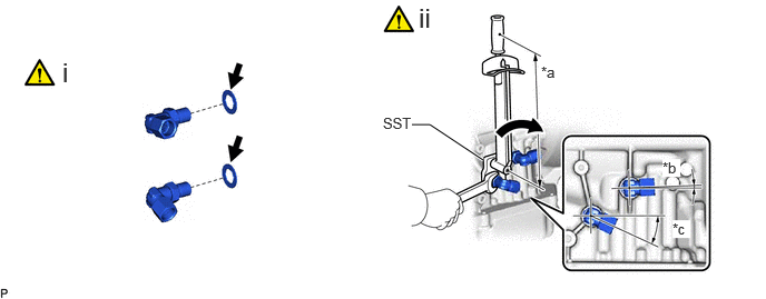
*a Torque Wrench Fulcrum Length *b -2° to 2°
*c 23° to 27° - -


i.

Coat 2 new O-rings with ATF and install them to the 2 oil cooler tube unions.


ii.

Using SST, install the 2 oil cooler tube unions to the automatic transmission case sub-assembly.

SST
09268-78010  

Torque:
Specified tightening torque : 29.4 N*m (300 kgf*cm, 22 ft.*lbf)

HINT:
·

Calculate the torque wrench reading when changing the fulcrum length of the torque wrench.

Click hereGeneral>INTRODUCTION>REPAIR INSTRUCTION>PRECAUTION

·

When using SST (fulcrum length of 34.5 mm (1.3583 in.)) + torque wrench (fulcrum length of 180 mm (7.0866 in.)): 24.7 N*m (252 kgf*cm, 18 ft.*lbf)


Hide 61.INSTALL BREATHER PLUG SUB-ASSEMBLY

a.
C458270C01
1.531,0.198 1.896,0.198 false 1.531,0.781 2.01,0.781 false 2.177,1.406 2.333,1.271 2.333,1.271 2.51,1.271 false 2.198,1.635 2.354,1.5 2.354,1.5 2.531,1.5 false 1.927,0.115 2.208,0.333 0.281,0.219 10 false *1 2.531,1.177 2.771,1.385 0.24,0.208 10 false *2 2.031,0.698 2.292,0.906 0.26,0.208 10 false *3 2.552,1.417 2.802,1.615 0.25,0.198 10 false *4 0.396,0.063 0.875,0.396 0.479,0.333 18 false i, ii 4.25,0.073 4.656,0.49 0.406,0.417 18 false iii
*1 No. 1 Breather Plug (ATM) *2 No. 2 Breather Plug (ATM)
*3 Breather Plug Hose *4 O-ring


i.

Install the No. 1 breather plug (ATM) and No. 2 breather plug (ATM) to the breather plug hose.


ii.

Coat a new O-ring with ATF, and install it to the No. 2 breather plug (ATM).


iii.

Install the breather plug sub-assembly to the automatic transmission assembly.


Hide 89530C 62.INSTALL TCM

Torque:
24.5 N*m (250 kgf*cm, 18 ft.*lbf)