AXLE AND DIFFERENTIAL FRONT DIFFERENTIAL CARRIER ASSEMBLY(w/ Differential Lock) REASSEMBLY
CAUTION / NOTICE / HINT
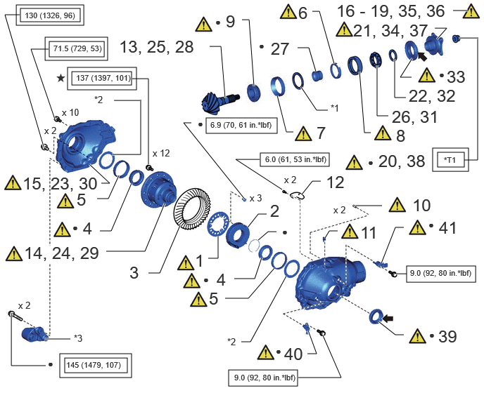
| Procedure | Part Name Code |

|

|

|
|
|---|---|---|---|---|---|
| 1 | INSTALL DIFFERENTIAL LOCK POSITION PLATE | - | ( ) |
- | - |
| 2 | INSTALL DIFFERENTIAL LOCK COIL | - | - | - | - |
| 3 | INSTALL DIFFERENTIAL RING GEAR | - | - | - | - |
| 4 | INSTALL FRONT DIFFERENTIAL CASE BEARING (INNER) | 41311A | () |
- | - |
| 5 | INSTALL FRONT DIFFERENTIAL CASE BEARING (OUTER) | 41311A | () |
- | - |
| 6 | INSTALL FRONT DIFFERENTIAL OIL STORAGE RING | 41115F | () |
- | - |
| 7 | INSTALL FRONT DRIVE PINION REAR TAPERED ROLLER BEARING (OUTER) | 41211B | () |
- | - |
| 8 | INSTALL FRONT DRIVE PINION FRONT RADIAL BALL BEARING (OUTER) | 41211A | () |
- | - |
| 9 | INSTALL FRONT DRIVE PINION REAR TAPERED ROLLER BEARING (INNER) | 41211B | () |
- | - |
| 10 | INSTALL FRONT DIFFERENTIAL CARRIER STRAIGHT PIN | 41111D | () |
- | - |
| 11 | INSTALL FRONT DIFFERENTIAL UNION | - | () |
- | - |
| 12 | INSTALL FRONT DIFFERENTIAL BREATHER PLUG OIL DEFLECTOR | 41183C | - | - | - |
| 13 | INSTALL DIFFERENTIAL DRIVE PINION | - | - | - | - |
| 14 | INSTALL FRONT NO. 1 DIFFERENTIAL CASE SUB-ASSEMBLY | 41301L | - | - | - |
| 15 | INSTALL FRONT DIFFERENTIAL CROSS SHAFT BEARING RETAINER | - | - | - | - |
| 16 | ADJUST DIFFERENTIAL DRIVE PINION PRELOAD | - | () |
- | - |
| 17 | ADJUST BACKLASH BETWEEN DIFFERENTIAL RING GEAR AND DIFFERENTIAL DRIVE PINION | - | () |
- | - |
| 18 | INSPECT TOTAL PRELOAD | - | () |
- | - |
| 19 | ADJUST TOOTH CONTACT BETWEEN RING GEAR AND DRIVE PINION | - | () |
- | - |
| 20 | REMOVE FRONT DRIVE PINION COMPANION FLANGE NUT | 41204E | () |
- | - |
| 21 | REMOVE FRONT DRIVE PINION COMPANION FLANGE SUB-ASSEMBLY | 41204D | () |
- | - |
| 22 | REMOVE FRONT DIFFERENTIAL DRIVE PINION OIL SLINGER | 41214C | - | - | - |
| 23 | REMOVE FRONT DIFFERENTIAL CROSS SHAFT BEARING RETAINER | - | - | - | - |
| 24 | REMOVE FRONT NO. 1 DIFFERENTIAL CASE SUB-ASSEMBLY | 41301L | () |
- | - |
| 25 | REMOVE DIFFERENTIAL DRIVE PINION | - | - | - | - |
| 26 | REMOVE FRONT DRIVE PINION FRONT RADIAL BALL BEARING (INNER) | 41211A | () |
- | - |
| 27 | INSTALL FRONT DIFFERENTIAL DRIVE PINION BEARING SPACER | 41231F | - | - | - |
| 28 | INSTALL DIFFERENTIAL DRIVE PINION | - | - | - | - |
| 29 | INSTALL FRONT NO. 1 DIFFERENTIAL CASE SUB-ASSEMBLY | 41301L | () |
- | - |
| 30 | INSTALL FRONT DIFFERENTIAL CROSS SHAFT BEARING RETAINER | - | () |
- | - |
| 31 | INSTALL FRONT DRIVE PINION FRONT RADIAL BALL BEARING (INNER) | 41211A | () |
- | - |
| 32 | INSTALL FRONT DIFFERENTIAL DRIVE PINION OIL SLINGER | 41214C | - | - | - |
| 33 | INSTALL FRONT DIFFERENTIAL CARRIER OIL SEAL | - | () |
- | - |
| 34 | INSTALL FRONT DRIVE PINION COMPANION FLANGE SUB-ASSEMBLY | 41204D | - | - | - |
| 35 | INSPECT TOTAL PRELOAD | - | () |
- | - |
| 36 | INSPECT DIFFERENTIAL RING GEAR AND DIFFERENTIAL DRIVE PINION BACKLASH | - | () |
- | - |
| 37 | INSPECT FRONT DRIVE PINION COMPANION FLANGE SUB-ASSEMBLY | 41204D | () |
- | - |
| 38 | STAKE DRIVE PINION COMPANION FLANGE NUT | - | - | - | - |
| 39 | FRONT DRIVE SHAFT OIL SEAL LH | 43420H | () |
- | - |
| 40 | INSTALL WIRING HARNESS CONNECTOR | 82H24B | () |
- | - |
| 41 | INSTALL NO. 1 4 WHEEL DRIVE POSITION SWITCH | 84546 | () |
- | - |
| *1 | DRIVE PINION WASHER | *2 | PLATE WASHER |
| *3 | FRONT DIFFERENTIAL SUPPORT ASSEMBLY | - | - |

|
Tightening torque for "Major areas involving basic vehicle performance such as moving/turning/stopping": N*m (kgf*cm, ft.*lbf) |

|
N*m (kgf*cm, ft.*lbf): Specified torque |

|
MP grease |

|
Hypoid gear oil |
| ● | Non-reusable part | ★ | Precoated part |
| *T1 | 451 (4599, 333) or less | - | - |
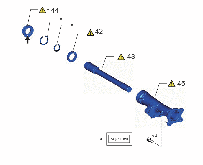
| Procedure | Part Name Code |
|
|
|
|
|---|---|---|---|---|---|
| 42 | INSTALL FRONT DIFFERENTIAL SIDE GEAR SHAFT BEARING RH | - | () |
- | - |
| 43 | INSTALL DIFFERENTIAL SIDE GEAR SHAFT SUB-ASSEMBLY RH | 41304F | - | - | - |
| 44 | INSTALL FRONT DRIVE SHAFT OIL SEAL RH | 41304P | () |
- | - |
| 45 | INSTALL DIFFERENTIAL EXTENSION FLANGE TUBE | 41321 | () |
- | - |
|
|
Tightening torque for "Major areas involving basic vehicle performance such as moving/turning/stopping": N*m (kgf*cm, ft.*lbf) |
|
MP Grease |
| ● | Non-reusable part | - | - |
PROCEDURE

 1.INSTALL DIFFERENTIAL LOCK POSITION PLATE
|
|
|

Using a T20 ''TORX'' socket wrench, install the differential lock position plate.
- Torque:
- 6.9 N*m (70 kgf*cm, 61 in.*lbf)
2.INSTALL DIFFERENTIAL LOCK COIL
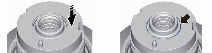

|
Install in this Direction | - | - |
3.INSTALL DIFFERENTIAL RING GEAR
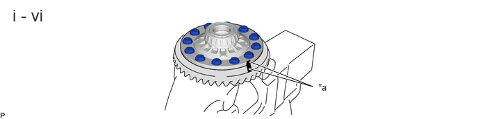
| *a | Matchmark | - | - |
Clean the contact surface of the differential case and differential ring gear.
Heat the differential ring gear in boiling water that is approximately 100°C (212°F).
Carefully remove the differential ring gear from the boiling water.
After the moisture on the differential ring gear has completely evaporated, quickly install the differential ring gear to the differential case.
Align the matchmarks on the differential ring gear and differential case.
After the ring gear cools down, apply thread lock adhesive to the 12 set bolts and install them.
- Thread lock:
-
Toyota Genuine Adhesive 1360K, Three Bond 1360K or equivalent
- Torque:
- 137 N*m (1397 kgf*cm, 101 ft.*lbf)
41311A 4.INSTALL FRONT DIFFERENTIAL CASE BEARING (INNER)

Using SST and a press, press the 2 front differential case bearings (inner) onto the differential case.
- SST
-
09950-60011 (09951-00520, 09951-00610)
09950-70010 (09951-07150)
41311A 5.INSTALL FRONT DIFFERENTIAL CASE BEARING (OUTER)
|
|
|
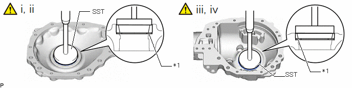
| *1 | Plate Washer | - | - |
Install a new plate washer to the shaft bearing retainer.
Using SST and a press, press in the front differential case bearing (outer) to the differential side bearing retainer.
- SST
-
09950-60021 (09951-00910)
09950-70010 (09951-07150)
Install a new plate washer to the differential carrier.
Using SST and a press, press in the front differential case bearing (outer) to the differential carrier.
- SST
-
09950-60021 (09951-00910)
09950-70010 (09951-07150)
41115F 6.INSTALL FRONT DIFFERENTIAL OIL STORAGE RING
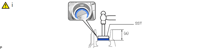
Using SSTand hammer, install the front differential oil storage ring.
- NOTICE:
-
Install the differential carrier assembly so that front differential oil storage ring does not overlap the oil passage.
- SST
-
09950-60021 (09951-00710)
- Standard front differential oil storage ring depth (A):
-
66.4 to 68.4 mm (2.615 to 2.692 in.)
41211B 7.INSTALL FRONT DRIVE PINION REAR TAPERED ROLLER BEARING (OUTER)
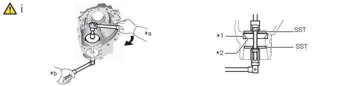
| *1 | Front Drive Pinion Rear Tapered Roller Bearing (Outer) | *2 | Drive Pinion Washer |
| *a | Turn | *b | Hold |
Using SST, install the drive pinion washer and front drive pinion rear tapered roller bearing (outer).
- SST
-
09950-60021 (09951-00720, 09951-00890)
09950-70010 (09951-07150)
- HINT:
-
First, install a drive pinion plate washer that has the same thickness as the removed drive pinion plate washer. After checking the tooth contact pattern, replace the drive pinion plate washer with one of a different thickness if necessary.
41211A 8.INSTALL FRONT DRIVE PINION FRONT RADIAL BALL BEARING (OUTER)
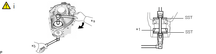
| *1 | Front Drive Pinion Front Radial Ball Bearing (Outer) | - | - |
| *a | Turn | *b | Hold |
Using SST, install the front drive pinion radial ball roller bearing (outer).
- SST
-
09950-60021 (09951-00720, 09951-00890)
41211B 9.INSTALL FRONT DRIVE PINION REAR TAPERED ROLLER BEARING (INNER)
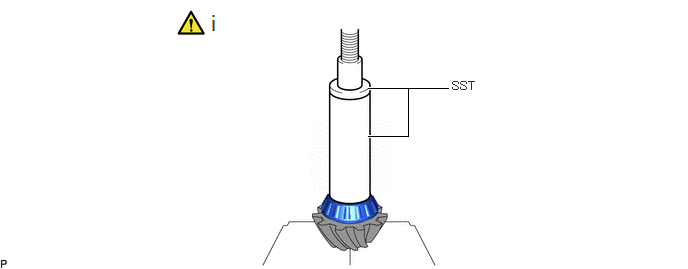
Using SST and a press, press the front drive pinion rear tapered roller bearing (inner) onto the differential drive pinion.
- SST
-
09950-60011 (09951-00610)
09308-14010
41111D 10.INSTALL FRONT DIFFERENTIAL CARRIER STRAIGHT PIN

Using a plastic-faced hammer, tap in the 2 straight pins until the protrusion height shown in the illustration is within the specification.
- Standard height (A):
-
9.5 to 10.0 mm (0.374 to 0.393 in.)
11.INSTALL FRONT DIFFERENTIAL UNION
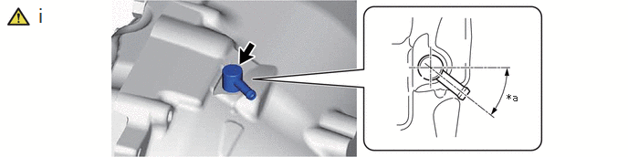
| *a | 36 to 42° | - | - |
Install the front differential union.
- HINT:
-
Make sure that the tabs of the front differential union are positioned within the area shown in the illustration.
41183C 12.INSTALL FRONT DIFFERENTIAL BREATHER PLUG OIL DEFLECTOR
- Torque:
- 6.0 N*m (61 kgf*cm, 53 in.*lbf)
13.INSTALL DIFFERENTIAL DRIVE PINION
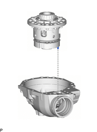
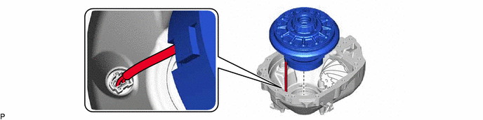
41301L 14.INSTALL FRONT NO. 1 DIFFERENTIAL CASE SUB-ASSEMBLY
|
|
|
15.INSTALL FRONT DIFFERENTIAL CROSS SHAFT BEARING RETAINER
|
|
|

Install the differential cross shaft bearing retainer and differential carrier assembly with the 10 bolts (A).
- Torque:
- 71.5 N*m (729 kgf*cm, 53 ft.*lbf)
Install the differential cross shaft bearing retainer and differential carrier assembly with the 2 bolts (B).
- Torque:
- 130 N*m (1326 kgf*cm, 96 ft.*lbf)
16.ADJUST DIFFERENTIAL DRIVE PINION PRELOAD
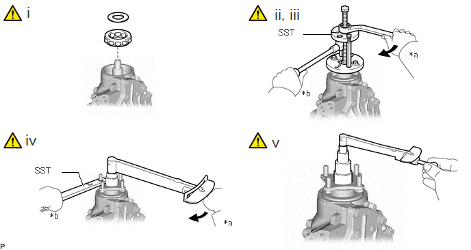
| *a | Turn | *b | Hold |
Install the front drive pinion front radial ball bearing (inner) and front differential drive pinion oil slinger.
Using SST, install the front drive pinion companion flange sub-assembly with dust deflector.
- SST
-
09950-30012 (09951-03010, 09953-03010, 09954-03010, 09955-03030, 09956-03020)
- NOTICE:
-
Before using SST (center bolt), apply hypoid gear oil to its threads and tip.
Adjust the differential drive pinion preload by tightening the front drive pinion companion flange nut.
Using SST to hold the front drive pinion companion flange sub-assembly with dust deflector in place, tighten the front drive pinion companion flange nut.
- SST
-
09330-00021 (09330-00030)
- Limit torque value:
-
451 N*m (4599 kgf*cm, 333 ft.*lbf) or less
- NOTICE:
-
·
As there is no spacer, tighten the nut a little at a time. Be careful not to overtighten it.
·Apply hypoid gear oil LSD to the drive pinion thread and nut seat face.
Using a torque wrench, measure the preload.
- Standard Preload (Starting Torque):
-
Item Specified Condition New bearing 3.40 to 3.90 N*m (35 to 39 kgf*cm, 31 to 34 in.*lbf) Reused bearing 3.25 to 3.57 N*m (34 to 36 kgf*cm, 29 to 31 in.*lbf)
- NOTICE:
-
·
For a more accurate measurement, rotate the bearing forward and backward several times before measuring.
·Record the differential drive pinion preload for the total preload measurement.
17.ADJUST BACKLASH BETWEEN DIFFERENTIAL RING GEAR AND DIFFERENTIAL DRIVE PINION

Using SST and a dial indicator, measure the ring gear backlash.
- SST
-
09564-33010
- Standard backlash:
-
0.17 to 0.27 mm (0.00670 to 0.0106 in.)
If the backlash is not within the specification, adjust it by either increasing or decreasing the thickness ofthe washers on both sides by an equal amount.
- HINT:
-
·
There should be no clearance between the plate washer and differential case.
·Make sure that there is ring gear backlash.
- Standard Washer Thickness:
-
Part No. Thickness mm (in.) Part No. Thickness mm (in.) 90564-65033 1.49 to 1.51 mm ( 0.0587 to 0.0594 in.) 90564-65055 1.93 to 1.95 mm ( 0.0760 to 0.0767 in.) 90564-65034 1.51 to 1.53 mm ( 0.0595 to 0.0602 in.) 90564-65056 1.95 to 1.97 mm ( 0.0768 to 0.0775 in.) 90564-65035 1.53 to 1.55 mm ( 0.0603 to 0.0610 in.) 90564-65057 1.97 to 1.99 mm ( 0.0776 to 0.0783 in.) 90564-65036 1.55 to 1.57 mm ( 0.0611 to 0.0618 in.) 90564-65058 1.99 to 2.01 mm ( 0.0784 to 0.0791 in.) 90564-65037 1.57 to 1.59 mm ( 0.0619 to 0.0625 in.) 90564-65059 2.01 to 2.03 mm ( 0.0792 to 0.0799 in.) 90564-65038 1.59 to 1.61 mm ( 0.0626 to 0.0633 in.) 90564-65060 2.03 to 2.05 mm ( 0.0800 to 0.0807 in.) 90564-65039 1.61 to 1.63 mm ( 0.0634 to 0.0641 in.) 90564-65061 2.05 to 2.07 mm ( 0.0808 to 0.0814 in.) 90564-65040 1.63 to 1.65 mm ( 0.0642 to 0.0649 in.) 90564-65062 2.07 to 2.09 mm ( 0.0815 to 0.0822 in.) 90564-65041 1.65 to 1.67 mm ( 0.0650 to 0.0657 in.) 90564-65063 2.09 to 2.11 mm ( 0.0823 to 0.0830 in.) 90564-65042 1.67 to 1.69 mm ( 0.0658 to 0.0665 in.) 90564-65064 2.11 to 2.13 mm ( 0.0831 to 0.0838 in.) 90564-65043 1.69 to 1.71 mm ( 0.0666 to 0.0673 in.) 90564-65065 2.13 to 2.15 mm ( 0.0839 to 0.0846 in.) 90564-65044 1.71 to 1.73 mm ( 0.0674 to 0.0681 in.) 90564-65066 2.15 to 2.17 mm ( 0.0847 to 0.0854 in.) 90564-65045 1.73 to 1.75 mm ( 0.0682 to 0.0688 in.) 90564-65067 2.17 to 2.19 mm ( 0.0855 to 0.0862 in.) 90564-65046 1.75 to 1.77 mm ( 0.0689 to 0.0696 in.) 90564-65068 2.19 to 2.21 mm ( 0.0863 to 0.0870 in.) 90564-65047 1.77 to 1.79 mm ( 0.0697 to 0.0704 in.) 90564-65069 2.21 to 2.23 mm ( 0.0871 to 0.0877 in.) 90564-65048 1.79 to 1.81 mm ( 0.0705 to 0.0712 in.) 90564-65070 2.23 to 2.25 mm ( 0.0878 to 0.0885 in.) 90564-65049 1.81 to 1.83 mm ( 0.0713 to 0.0720 in.) 90564-65071 2.25 to 2.27 mm ( 0.0886 to 0.0893 in.) 90564-65050 1.83 to 1.85 mm ( 0.0721 to 0.0728 in.) 90564-65072 2.27 to 2.29 mm ( 0.0894 to 0.0901 in.) 90564-65051 1.85 to 1.87 mm ( 0.0729 to 0.0736 in.) 90564-65073 2.29 to 2.31 mm ( 0.0902 to 0.0909 in.) 90564-65052 1.87 to 1.89 mm ( 0.0737 to 0.0744 in.) 90564-65074 2.31 to 2.33 mm ( 0.0910 to 0.0917 in.) 90564-65053 1.89 to 1.91 mm ( 0.0745 to 0.0751 in.) 90564-65075 2.33 to 2.35 mm ( 0.0918 to 0.0925 in.) 90564-65054 1.91 to 1.93 mm ( 0.0752 to 0.0759 in.) - -
18.INSPECT TOTAL PRELOAD
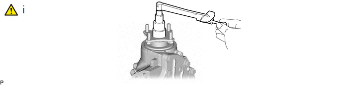
Using a torque wrench, measure the preload with the teeth of the drive pinion and ring gear in contact.
- Standard Total Preload (Starting Torque):
-
Reduction Ratio Item Specified Condition 3.307 New bearing 4.61 to 5.89 N*m (48 to 60 kgf*cm, 41 to 52 in.*lbf) Reused bearing 4.43 to 5.52 N*m (46 to 56 kgf*cm, 40 to 48 in.*lbf) 4.300 New bearing 4.33 to 5.43 N*m (45 to 55 kgf*cm, 39 to 48 in.*lbf) Reused bearing 4.16 to 5.07 N*m (43 to 51 kgf*cm, 37 to 44 in.*lbf)
If necessary, disassemble and inspect the differential.
19.ADJUST TOOTH CONTACT BETWEEN RING GEAR AND DRIVE PINION
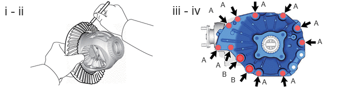
Remove the differential case bearing retainer and differential case.
Coat 3 or 4 teeth at 3 different positions on the ring gear with Prussian blue.
Install the differential case and differential case bearing retainer.
- Torque:
- Bolt A : 71.5 N*m (729 kgf*cm, 53 ft.*lbf)
- Bolt B : 130 N*m (1326 kgf*cm, 96 ft.*lbf)
- NOTICE:
-
After fully tightening all bolts, check that all bolts are tightened to the specified torque.
Hold the companion flange firmly in place and rotate the ring gear in both directions.
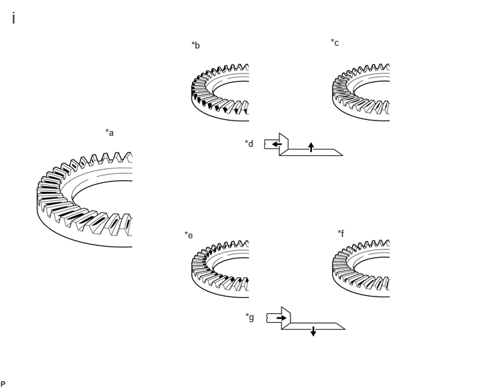
| *a | Proper Contact | *b | Heel Contact |
| *c | Face Contact | *d | Select an adjusting washer that will shift the drive pinion closer to the ring gear (*b, *c) |
| *e | Toe Contact | *f | Flank Contact |
| *g | Select an adjusting washer that will shift the drive pinion away from the ring gear (*e, *f) | - | - |
Inspect the tooth contact pattern.
- Standard Washer Thickness:
- Drive Pinion Side:
-
Part No. Thickness mm (in.) Part No. Thickness mm (in.) 90564-68104 1.815 to 1.835 mm ( 0.0715 to 0.0722 in.) 90564-68114 2.065 to 2.085 mm ( 0.0813 to 0.0820 in.) 90564-68105 1.84 to 1.86 mm ( 0.0725 to 0.0732 in.) 90564-68115 2.09 to 2.11 mm ( 0.0823 to 0.0830 in.) 90564-68106 1.865 to 1.885 mm ( 0.0735 to 0.0742 in.) 90564-68116 2.115 to 2.135 mm ( 0.0833 to 0.0840 in.) 90564-68107 1.89 to 1.91 mm ( 0.0745 to 0.0751 in.) 90564-68117 2.14 to 2.16 mm ( 0.0843 to 0.0850 in.) 90564-68108 1.915 to 1.935 mm ( 0.0754 to 0.0761 in.) 90564-68118 2.165 to 2.185 mm ( 0.0853 to 0.0860 in.) 90564-68109 1.94 to 1.96 mm ( 0.0764 to 0.0771 in.) 90564-68119 2.19 to 2.21 mm ( 0.0863 to 0.0870 in.) 90564-68110 1.965 to 1.985 mm ( 0.0774 to 0.0781 in.) 90564-68120 2.215 to 2.235 mm ( 0.0873 to 0.0879 in.) 90564-68111 1.99 to 2.01 mm ( 0.0784 to 0.0791 in.) 90564-68121 2.24 to 2.26 mm ( 0.0882 to 0.0889 in.) 90564-68112 2.015 to 2.035 mm ( 0.0794 to 0.0801 in.) 90564-68122 2.265 to 2.285 mm ( 0.0892 to 0.0899 in.) 90564-68113 2.04 to 2.06 mm ( 0.0804 to 0.0811 in.) - -
- Side Gear Side:
-
Part No. Thickness mm (in.) Part No. Thickness mm (in.) 90564-65033 1.49 to 1.51 mm ( 0.0587 to 0.0594 in.) 90564-65055 1.93 to 1.95 mm ( 0.0760 to 0.0767 in.) 90564-65034 1.51 to 1.53 mm ( 0.0595 to 0.0602 in.) 90564-65056 1.95 to 1.97 mm ( 0.0768 to 0.0775 in.) 90564-65035 1.53 to 1.55 mm ( 0.0603 to 0.0610 in.) 90564-65057 1.97 to 1.99 mm ( 0.0776 to 0.0783 in.) 90564-65036 1.55 to 1.57 mm ( 0.0611 to 0.0618 in.) 90564-65058 1.99 to 2.01 mm ( 0.0784 to 0.0791 in.) 90564-65037 1.57 to 1.59 mm ( 0.0619 to 0.0625 in.) 90564-65059 2.01 to 2.03 mm ( 0.0792 to 0.0799 in.) 90564-65038 1.59 to 1.61 mm ( 0.0626 to 0.0633 in.) 90564-65060 2.03 to 2.05 mm ( 0.0800 to 0.0807 in.) 90564-65039 1.61 to 1.63 mm ( 0.0634 to 0.0641 in.) 90564-65061 2.05 to 2.07 mm ( 0.0808 to 0.0814 in.) 90564-65040 1.63 to 1.65 mm ( 0.0642 to 0.0649 in.) 90564-65062 2.07 to 2.09 mm ( 0.0815 to 0.0822 in.) 90564-65041 1.65 to 1.67 mm ( 0.0650 to 0.0657 in.) 90564-65063 2.09 to 2.11 mm ( 0.0823 to 0.0830 in.) 90564-65042 1.67 to 1.69 mm ( 0.0658 to 0.0665 in.) 90564-65064 2.11 to 2.13 mm ( 0.0831 to 0.0838 in.) 90564-65043 1.69 to 1.71 mm ( 0.0666 to 0.0673 in.) 90564-65065 2.13 to 2.15 mm ( 0.0839 to 0.0846 in.) 90564-65044 1.71 to 1.73 mm ( 0.0674 to 0.0681 in.) 90564-65066 2.15 to 2.17 mm ( 0.0847 to 0.0854 in.) 90564-65045 1.73 to 1.75 mm ( 0.0682 to 0.0688 in.) 90564-65067 2.17 to 2.19 mm ( 0.0855 to 0.0862 in.) 90564-65046 1.75 to 1.77 mm ( 0.0689 to 0.0696 in.) 90564-65068 2.19 to 2.21 mm ( 0.0863 to 0.0870 in.) 90564-65047 1.77 to 1.79 mm ( 0.0697 to 0.0704 in.) 90564-65069 2.21 to 2.23 mm ( 0.0871 to 0.0877 in.) 90564-65048 1.79 to 1.81 mm ( 0.0705 to 0.0712 in.) 90564-65070 2.23 to 2.25 mm ( 0.0878 to 0.0885 in.) 90564-65049 1.81 to 1.83 mm ( 0.0713 to 0.0720 in.) 90564-65071 2.25 to 2.27 mm ( 0.0886 to 0.0893 in.) 90564-65050 1.83 to 1.85 mm ( 0.0721 to 0.0728 in.) 90564-65072 2.27 to 2.29 mm ( 0.0894 to 0.0901 in.) 90564-65051 1.85 to 1.87 mm ( 0.0729 to 0.0736 in.) 90564-65073 2.29 to 2.31 mm ( 0.0902 to 0.0909 in.) 90564-65052 1.87 to 1.89 mm ( 0.0737 to 0.0744 in.) 90564-65074 2.31 to 2.33 mm ( 0.0910 to 0.0917 in.) 90564-65053 1.89 to 1.91 mm ( 0.0745 to 0.0751 in.) 90564-65075 2.33 to 2.35 mm ( 0.0918 to 0.0925 in.) 90564-65054 1.91 to 1.93 mm ( 0.0752 to 0.0759 in.) - -
If the teeth are not engaged properly, use the following chart to select the appropriate washer for correction.
41204E 20.REMOVE FRONT DRIVE PINION COMPANION FLANGE NUT
|
|
Click here() |
41204D 21.REMOVE FRONT DRIVE PINION COMPANION FLANGE SUB-ASSEMBLY
|
|
Click here() |
41214C 22.REMOVE FRONT DIFFERENTIAL DRIVE PINION OIL SLINGER
23.REMOVE FRONT DIFFERENTIAL CROSS SHAFT BEARING RETAINER
41301L 24.REMOVE FRONT NO. 1 DIFFERENTIAL CASE SUB-ASSEMBLY
|
|
Click here() |
25.REMOVE DIFFERENTIAL DRIVE PINION
41211A 26.REMOVE FRONT DRIVE PINION FRONT RADIAL BALL BEARING (INNER)
|
|
Click here() |
41231F 27.INSTALL FRONT DIFFERENTIAL DRIVE PINION BEARING SPACER

28.INSTALL DIFFERENTIAL DRIVE PINION
41301L 29.INSTALL FRONT NO. 1 DIFFERENTIAL CASE SUB-ASSEMBLY
|
|
Click here() |
30.INSTALL FRONT DIFFERENTIAL CROSS SHAFT BEARING RETAINER
|
|
|
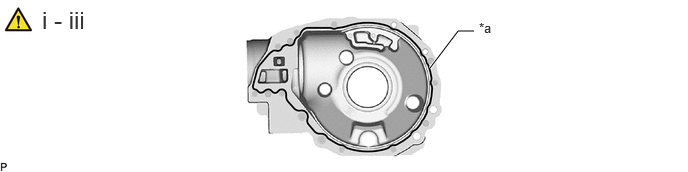
| *a | Seal Packing | - | - |
Remove any old seal packing material from the differential side bearing retainer.
- NOTICE:
-
Do not drop oil on the contact surfaces of the differential carrier and differential side bearing retainer.
Clean residual seal packing material on the contact surface using gasoline or alcohol.
Apply seal packing to the differential side bearing retainer as shown in the illustration.
- Seal packing:
-
Toyota Genuine seal packing 1281, Three Bond 1281 or equivalent
- HINT:
-
Install the differential side bearing retainer within 3 minutes after applying seal packing.
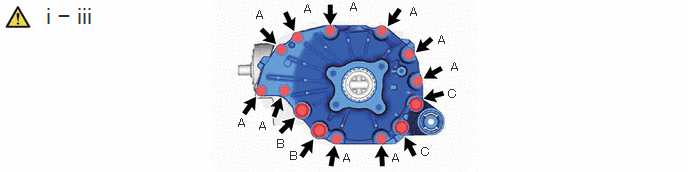
Install the differential cross shaft bearing retainer and differential carrier assembly with the 10 bolts (A).
- Torque:
- 71.5 N*m (729 kgf*cm, 53 ft.*lbf)
Install the differential cross shaft bearing retainer and differential carrier assembly with the 2 bolts (B).
- Torque:
- 130 N*m (1326 kgf*cm, 96 ft.*lbf)
Install the differential cross shaft bearing retainer and differential support with the 2 new bolts (C).
- Torque:
- 145 N*m (1479 kgf*cm, 107 ft.*lbf)
41211A 31.INSTALL FRONT DRIVE PINION FRONT RADIAL BALL BEARING (INNER)

41214C 32.INSTALL FRONT DIFFERENTIAL DRIVE PINION OIL SLINGER
33.INSTALL FRONT DIFFERENTIAL CARRIER OIL SEAL
|
|
Click here() |
41204D 34.INSTALL FRONT DRIVE PINION COMPANION FLANGE SUB-ASSEMBLY
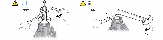
| *a | Turn | *b | Hold |
Using SST, install the rear drive pinion companion flange sub-assembly with dust deflector.
- SST
-
09950-30012 (09951-03010, 09953-03010, 09954-03010, 09955-03030, 09956-03040)
- NOTICE:
-
Before using SST (center bolt), apply hypoid gear oil to its threads and tip.
Apply hypoid gear oil LSD to the drive pinion thread and nut seat face.
Using SST to hold the companion flange in place, install a new nut.
- SST
-
09330-00021 (09330-00030)
- Limit torque value:
-
451 N*m (4599 kgf*cm, 333 ft.*lbf) or less
35.INSPECT TOTAL PRELOAD

Using a torque wrench, measure the preload with the teeth of the drive pinion and ring gear in contact.
- Standard Total Preload (Starting Torque):
-
Reduction Ratio Item Specified Condition 3.307 New bearing 5.04 to 6.32 N*m (52 to 64 kgf*cm, 45 to 55 in.*lbf) Reused bearing 4.86 to 5.95 N*m (50 to 60 kgf*cm, 44 to 52 in.*lbf) 4.300 New bearing 4.76 to 5.86 N*m (49 to 59 kgf*cm, 43 to 51 in.*lbf) Reused bearing 4.59 to 5.50 N*m (47 to 56 kgf*cm, 41 to 48 in.*lbf)
If necessary, disassemble and inspect the differential.
36.INSPECT DIFFERENTIAL RING GEAR AND DIFFERENTIAL DRIVE PINION BACKLASH

Using SST and a dial indicator, measure the ring gear backlash.
- SST
-
09564-32011
- Standard backlash:
-
0.17 to 0.27 mm (0.00670 to 0.0106 in.)
If the backlash is not within the specification, adjust the side bearing preload.
41204D 37.INSPECT FRONT DRIVE PINION COMPANION FLANGE SUB-ASSEMBLY
38.STAKE FRONT DRIVE PINION COMPANION FLANGE NUT

43420H 39.INSTALL FRONT DRIVE SHAFT OIL SEAL LH
|
|
Click here() |
82H24B 40.INSTALL WIRING HARNESS CONNECTOR
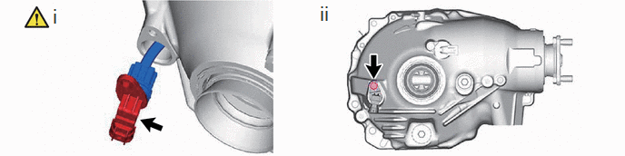
Connect the new wiring harness connector.
- NOTICE:
-
Do not forcibly pull the wiring harness connector.
Instal the bolt.
- Torque:
- 9.0 N*m (92 kgf*cm, 80 in.*lbf)
84546 41.INSTALL NO. 1 4 WHEEL DRIVE POSITION SWITCH
|
|
|

Install a new No. 1 4 wheel drive position switch with the bolt.
- NOTICE:
-
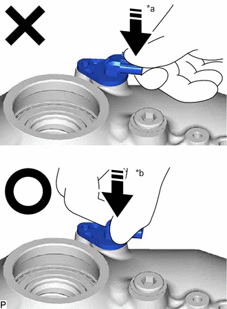 2.219,0.042 2.531,0.24 0.313,0.198 10 false *a 2.052,2.531 2.365,2.729 0.313,0.198 10 false *b
*a NG *b OK
-
When inserting the No. 1 4 wheel drive position switch into the differential carrier assembly, do not push it in by applying a weight to the upper surface of the connector as shown in the figure (* a). As shown in the figure (* b), support and assemble the connector neck.
- Torque:
- 9.0 N*m (92 kgf*cm, 80 in.*lbf)
42.INSTALL FRONT DIFFERENTIAL SIDE GEAR SHAFT BEARING RH
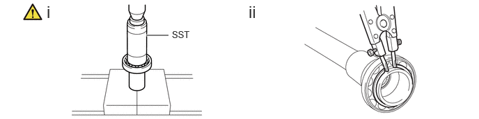
Using SST and a press, press in the front differential side gear shaft bearing RH.
- SST
-
09223-00010
Using a snap ring expander, install the snap ring.
41304F 43.INSTALL DIFFERENTIAL SIDE GEAR SHAFT SUB-ASSEMBLY RH
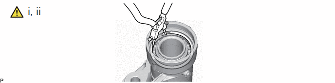
Install the differential side gear shaft sub-assembly RH to the front differential tube assembly.
Using a snap ring pliers, install a new snap ring.
- HINT:
-
Install the snap ring securely.
43410M 44.INSTALL FRONT DRIVE SHAFT OIL SEAL RH
|
|
Click here() |
41321 45.INSTALL DIFFERENTIAL EXTENSION FLANGE TUBE
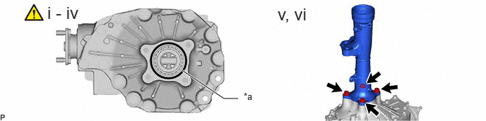
| *a | Seal Packing | - | - |
Remove any old seal packing material on the contact surfaces of the differential and clutch case.
- NOTICE:
-
Do not drop oil on the contact surfaces of the differential and clutch case.
Clean residual seal packing material on the contact surface using gasoline or alcohol.
Apply seal packing to the differential as shown in the illustration.
- Seal packing:
-
Toyota Genuine seal packing 1281, Three Bond 1281 or equivalent
- HINT:
-
Install the differential tube within 3 minutes after applying seal packing.
Install the front differential tube to the differential.
Clean the threads of the 4 bolts and retainer bolt holes with toluene or trichloroethylene.
Install the 4 bolts.
- Torque:
- 73 N*m (744 kgf*cm, 54 ft.*lbf)