Home › Drivetrain › AJA0F (AUTOMATIC TRANSMISSION / TRANSAXLE) › AUTOMATIC TRANSMISSION SYSTEM (for F33A-FTV) › from 2021.07
RM38G0E _52 Drivetrain _100435 AJA0F AUTOMATIC TRANSMISSION / TRANSAXLE _0488019 AUTOMATIC TRANSMISSION SYSTEM(for F33A-FTV) J

AJA0F AUTOMATIC TRANSMISSION / TRANSAXLE  AUTOMATIC TRANSMISSION SYSTEM(for F33A-FTV)  Drive Mode Select Switch Circuit  


DESCRIPTION

Each mode can be switched with the integration control & panel sub-assembly.

WIRING DIAGRAM
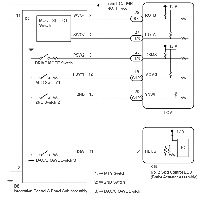
C463543E01
5.802,0.146 6.24,0.344 0.438,0.198 10 false 12 V 5.802,1.5 6.313,1.698 0.51,0.198 10 false 12 V 6.052,4.417 6.604,4.625 0.552,0.208 10 false 12 V 6.208,4.969 6.521,5.167 0.313,0.198 10 false IC 5.615,3.771 6.073,3.969 0.458,0.198 10 false ECM 2.51,0.438 3.125,0.635 0.615,0.198 10 false SWO4 2.51,1.104 3.125,1.302 0.615,0.198 10 false SWO2 2.51,1.802 3.125,2 0.615,0.198 10 false PSW2 2.635,3.146 3.25,3.344 0.615,0.198 10 false 2ND 2.583,5.104 3.198,5.302 0.615,0.198 10 false HSW 3.063,0.448 3.219,0.646 0.156,0.198 10 false 3 3.063,1.115 3.219,1.313 0.156,0.198 10 false 2 3.063,1.802 3.219,2 0.156,0.198 10 false 5 3.052,3.146 3.427,3.365 0.375,0.219 10 false 13 3.063,5.104 3.438,5.323 0.375,0.219 10 false 11 0.604,5.646 0.979,5.865 0.375,0.219 10 false 8 0.865,5.792 1.49,5.99 0.625,0.198 10 false E 4.583,0.552 4.958,0.771 0.375,0.219 10 false B70 4.625,0.344 4.938,0.542 0.313,0.198 10 false 29 4.969,0.438 5.542,0.635 0.573,0.198 10 false ROTB 4.625,1.021 4.938,1.219 0.313,0.198 10 false 27 4.969,1.104 5.542,1.302 0.573,0.198 10 false ROTA 4.99,1.792 5.604,1.99 0.615,0.198 10 false DSMS 4.635,1.708 4.948,1.906 0.313,0.198 10 false 28 4.625,3.052 4.938,3.25 0.313,0.198 10 false 20 4.969,3.146 5.583,3.344 0.615,0.198 10 false SNWI 1.219,3.417 2.75,3.615 1.531,0.198 10 false 2ND Switch*2 1.198,2.073 2.729,2.271 1.531,0.198 10 false DRIVE MODE Switch 1.24,5.406 2.771,5.604 1.531,0.198 10 false DAC/CRAWL Switch*3 0.469,6.458 4.448,6.656 3.979,0.198 10 false Integration Control & Panel Sub-assembly 5.167,5.813 6.813,6.406 1.646,0.594 10 false No. 2 Skid Control ECU (Brake Actuator Assembly) 3.677,0.031 4.594,0.417 0.917,0.385 10 false from ECU-IGR NO. 1 Fuse 0.552,0.438 1.146,0.635 0.594,0.198 10 false 14 0.844,0.552 1.458,0.75 0.615,0.198 10 false IG 1.344,0.615 2.375,1.271 1.031,0.656 10 false MODE SELECT Switch 4.677,5.094 5.052,5.313 0.375,0.219 10 false 34 4.969,5.094 5.583,5.292 0.615,0.198 10 false HDCS 5.156,5.625 5.531,5.844 0.375,0.219 10 false B19 0.469,6.292 0.844,6.51 0.375,0.219 10 false I88 1.219,2.74 2.75,2.938 1.531,0.198 10 false MTS Switch*1 3.031,2.458 3.344,2.656 0.313,0.198 10 false 12 2.5,2.458 3.115,2.656 0.615,0.198 10 false PSW1 4.979,2.469 5.594,2.667 0.615,0.198 10 false MCMS 4.615,2.375 4.927,2.573 0.313,0.198 10 false 19 3.198,5.854 5.802,6.052 2.604,0.198 10 false *1: w/ MTS Switch 3.198,6.156 5.802,6.354 2.604,0.198 10 false *2: w/ 2ND Switch 3.198,6.469 6.719,6.667 3.521,0.198 10 false *3: w/ DAC/CRAWL Switch 4.573,1.229 4.948,1.448 0.375,0.219 10 false B70 4.573,1.917 4.948,2.135 0.375,0.219 10 false B70 4.531,2.583 5.146,2.781 0.615,0.198 10 false C139 4.531,3.271 5.146,3.469 0.615,0.198 10 false C139

PROCEDURE

1.CHECK THE PROBLEM SYMPTOMS
a.

Check each symptom by checking the suspected areas in the table below.


Result:
Result Proceed to
DRIVE MODE switch system malfunction A
MTS switch system malfunction B
2ND switch system malfunction C
DAC/CRAWL switch system malfunction D


A

2.CHECK HARNESS AND CONNECTOR (IG VOLTAGE)

B

6.CHECK HARNESS AND CONNECTOR (IG VOLTAGE)

C

10.CHECK HARNESS AND CONNECTOR (INTEGRATION CONTROL & PANEL SUB-ASSEMBLY - BODY GROUND)

D

13.CHECK OPERATION AND CONDITION
2.CHECK HARNESS AND CONNECTOR (IG VOLTAGE)
a.

Disconnect the integration control & panel sub-assembly connector.


b.

Turn the ignition switch to ON.


c.

Measure the voltage according to the value(s) in the table below.

Standard Voltage:
Tester Connection Condition Specified Condition

Click Location & Routing(I88)Location & Routing

Click Connector(I88)Instrument Panel>Instrument Panel Wire / Mobile Wireless Charger Cord / No. 1 Navigation Wire / No. 2 Instrument Panel Wire / No. 5 Instrument Panel Wire / Telephone Computer Wire>Integration Control and Panel Sub-Assembly

I88-14 (IG) - Body ground Ignition switch ON 11 to 14 V


d.

Turn the ignition switch off.


e.

Measure the resistance according to the value(s) in the table below.

Standard Resistance:
Tester Connection Condition Specified Condition

Click Location & Routing(I88)Location & Routing

Click Connector(I88)Instrument Panel>Instrument Panel Wire / Mobile Wireless Charger Cord / No. 1 Navigation Wire / No. 2 Instrument Panel Wire / No. 5 Instrument Panel Wire / Telephone Computer Wire>Integration Control and Panel Sub-Assembly

I88-8 (E) - Body ground Always Below 1 Ω


Result:
Proceed to
OK
NG


OK

3.INSPECT INTEGRATION CONTROL & PANEL SUB-ASSEMBLY

NG

REPAIR OR REPLACE HARNESS OR CONNECTOR (INTEGRATION CONTROL & PANEL SUB-ASSEMBLY POWER SOURCE CIRCUIT)

3.INSPECT INTEGRATION CONTROL & PANEL SUB-ASSEMBLY

OK

4.CHECK HARNESS AND CONNECTOR (INTEGRATION CONTROL & PANEL SUB-ASSEMBLY - ECM)

NG

REPLACE INTEGRATION CONTROL & PANEL SUB-ASSEMBLY

4.CHECK HARNESS AND CONNECTOR (INTEGRATION CONTROL & PANEL SUB-ASSEMBLY - ECM)
a.

Disconnect the ECM connector.


b.

Measure the resistance according to the value(s) in the table below.

Standard Resistance:
Tester Connection Switch Condition Specified Condition

Click Location & Routing(B70)Location & Routing

Click Connector(B70)Engine Compartment>Engine Room Main Wire / Lamp Wire / No. 2 Engine Room Wire / No. 2 Lamp Wire / No. 3 Engine Room Wire / No. 6 Engine Room Wire / Washer Wiring Assembly>ECM

B70-28 (DSMS) - Body ground DRIVE MODE switch pushed 138 Ω or less
B70-28 (DSMS) - Body ground DRIVE MODE switch not pushed 10 kΩ or higher


Result:
Proceed to
OK
NG


OK

5.INSPECT INTEGRATION CONTROL & PANEL SUB-ASSEMBLY

NG

REPAIR OR REPLACE HARNESS OR CONNECTOR

5.INSPECT INTEGRATION CONTROL & PANEL SUB-ASSEMBLY
a.

Operate the DRIVE MODE switch to switch to drive mode select mode.


b.

Operate the MODE SELECT switch.

OK:

The drive mode select of the meter display changes according to the operation of the MODE SELECT switch.


Result:
Proceed to
OK
NG


OK

NG

REPLACE INTEGRATION CONTROL & PANEL SUB-ASSEMBLY

6.CHECK HARNESS AND CONNECTOR (IG VOLTAGE)
a.

Disconnect the integration control & panel sub-assembly connector.


b.

Turn the ignition switch to ON.


c.

Measure the voltage according to the value(s) in the table below.

Standard Voltage:
Tester Connection Condition Specified Condition

Click Location & Routing(I88)Location & Routing

Click Connector(I88)Instrument Panel>Instrument Panel Wire / Mobile Wireless Charger Cord / No. 1 Navigation Wire / No. 2 Instrument Panel Wire / No. 5 Instrument Panel Wire / Telephone Computer Wire>Integration Control and Panel Sub-Assembly

I88-14 (IG) - Body ground Ignition switch ON 11 to 14 V


d.

Turn the ignition switch off.


e.

Measure the resistance according to the value(s) in the table below.

Standard Resistance:
Tester Connection Condition Specified Condition

Click Location & Routing(I88)Location & Routing

Click Connector(I88)Instrument Panel>Instrument Panel Wire / Mobile Wireless Charger Cord / No. 1 Navigation Wire / No. 2 Instrument Panel Wire / No. 5 Instrument Panel Wire / Telephone Computer Wire>Integration Control and Panel Sub-Assembly

I88-8 (E) - Body ground Always Below 1 Ω


Result:
Proceed to
OK
NG


OK

7.INSPECT INTEGRATION CONTROL & PANEL SUB-ASSEMBLY

NG

REPAIR OR REPLACE HARNESS OR CONNECTOR (INTEGRATION CONTROL & PANEL SUB-ASSEMBLY POWER SOURCE CIRCUIT)

7.INSPECT INTEGRATION CONTROL & PANEL SUB-ASSEMBLY

OK

8.CHECK HARNESS AND CONNECTOR (DRIVE MODE SWITCH ASSEMBLY - ECM)

NG

REPLACE INTEGRATION CONTROL & PANEL SUB-ASSEMBLY

8.CHECK HARNESS AND CONNECTOR (DRIVE MODE SWITCH ASSEMBLY - ECM)
a.

Disconnect the ECM connector.


b.

Measure the resistance according to the value(s) in the table below.

Standard Resistance:
Tester Connection Switch Condition Specified Condition

Click Location & Routing(C139)Location & Routing

Click Connector(C139)Engine Compartment>Connecting Wire / Cooling Fan Wire / Engine Wire / Fuel Pump Motor Wire / No. 1 Connecting Wire / No. 10 Engine Wire / No. 2 Connecting Wire / No. 3 Connecting Wire / No. 4 Connecting Wire / Sensor Wire / Turbocharger Wire>ECM

C139-19 (MCMS) - Body ground MTS switch pushed 138 Ω or less
C139-19 (MCMS) - Body ground MTS switch not pushed 10 kΩ or higher


Result:
Proceed to
OK
NG


OK

9.INSPECT INTEGRATION CONTROL & PANEL SUB-ASSEMBLY

NG

REPAIR OR REPLACE HARNESS OR CONNECTOR

9.INSPECT INTEGRATION CONTROL & PANEL SUB-ASSEMBLY
a.

Operate the MTS switch to switch to multi-terrain select mode.


b.

Operate the MODE SELECT switch.

OK:

The multi-terrain select of the meter display changes according to the operation of the MODE SELECT switch.


Result:
Proceed to
OK
NG


OK

NG

REPLACE INTEGRATION CONTROL & PANEL SUB-ASSEMBLY

10.CHECK HARNESS AND CONNECTOR (INTEGRATION CONTROL & PANEL SUB-ASSEMBLY - BODY GROUND)
a.

Disconnect the integration control & panel sub-assembly connector.


b.

Measure the resistance according to the value(s) in the table below.

Standard Resistance:
Tester Connection Condition Specified Condition

Click Location & Routing(I88)Location & Routing

Click Connector(I88)Instrument Panel>Instrument Panel Wire / Mobile Wireless Charger Cord / No. 1 Navigation Wire / No. 2 Instrument Panel Wire / No. 5 Instrument Panel Wire / Telephone Computer Wire>Integration Control and Panel Sub-Assembly

I88-8 (E) - Body ground Always Below 1 Ω


Result:
Proceed to
OK
NG


OK

11.INSPECT INTEGRATION CONTROL & PANEL SUB-ASSEMBLY

NG

REPAIR OR REPLACE HARNESS OR CONNECTOR

11.INSPECT INTEGRATION CONTROL & PANEL SUB-ASSEMBLY

OK

12.CHECK HARNESS AND CONNECTOR (DRIVE MODE SWITCH ASSEMBLY - ECM)

NG

REPLACE INTEGRATION CONTROL & PANEL SUB-ASSEMBLY

12.CHECK HARNESS AND CONNECTOR (DRIVE MODE SWITCH ASSEMBLY - ECM)
a.

Disconnect the ECM connector.


b.

Measure the resistance according to the value(s) in the table below.

Standard Resistance:
Tester Connection Switch Condition Specified Condition

Click Location & Routing(C139)Location & Routing

Click Connector(C139)Engine Compartment>Connecting Wire / Cooling Fan Wire / Engine Wire / Fuel Pump Motor Wire / No. 1 Connecting Wire / No. 10 Engine Wire / No. 2 Connecting Wire / No. 3 Connecting Wire / No. 4 Connecting Wire / Sensor Wire / Turbocharger Wire>ECM

C139-20 (SNWI) - Body ground 2ND switch pushed 66 Ω or less
C139-20 (SNWI) - Body ground 2ND switch not pushed 10 kΩ or higher


Result:
Proceed to
OK
NG


OK

NG

REPAIR OR REPLACE HARNESS OR CONNECTOR

13.CHECK OPERATION AND CONDITION
a.

Operation conditions for downhill assist control.

·

Transfer position in H4

·

Shift lever not in P

·

Front differential lock and rear differential lock not selected

·

Accelerator pedal and brake pedal not depressed

·

Driving uphill at a vehicle speed of 30 km/h (19 mph) or lower


b.

Operation conditions for crawl control.

·

Transfer position in L4

·

Shift lever not in P or N

·

Driver side door closed

·

VSC system normal

·

2ND start mode off

·

Parking brake released

·

Engine started


Result:
Proceed to
NEXT


NEXT

14.CHECK HARNESS AND CONNECTOR (IG VOLTAGE)
a.

Disconnect the integration control & panel sub-assembly connector.


b.

Turn the ignition switch to ON.


c.

Measure the voltage according to the value(s) in the table below.

Standard Voltage:
Tester Connection Condition Specified Condition

Click Location & Routing(I88)Location & Routing

Click Connector(I88)Instrument Panel>Instrument Panel Wire / Mobile Wireless Charger Cord / No. 1 Navigation Wire / No. 2 Instrument Panel Wire / No. 5 Instrument Panel Wire / Telephone Computer Wire>Integration Control and Panel Sub-Assembly

I88-14 (IG) - Body ground Ignition switch ON 11 to 14 V


d.

Turn the ignition switch off.


e.

Measure the resistance according to the value(s) in the table below.

Standard Resistance:
Tester Connection Condition Specified Condition

Click Location & Routing(I88)Location & Routing

Click Connector(I88)Instrument Panel>Instrument Panel Wire / Mobile Wireless Charger Cord / No. 1 Navigation Wire / No. 2 Instrument Panel Wire / No. 5 Instrument Panel Wire / Telephone Computer Wire>Integration Control and Panel Sub-Assembly

I88-8 (E) - Body ground Always Below 1 Ω


Result:
Proceed to
OK
NG


OK

15.INSPECT INTEGRATION CONTROL & PANEL SUB-ASSEMBLY

NG

REPAIR OR REPLACE HARNESS OR CONNECTOR (INTEGRATION CONTROL & PANEL SUB-ASSEMBLY POWER SOURCE CIRCUIT)

15.INSPECT INTEGRATION CONTROL & PANEL SUB-ASSEMBLY

OK

16.CHECK HARNESS AND CONNECTOR (INTEGRATION CONTROL & PANEL SUB-ASSEMBLY - BRAKE ACTUATOR ASSEMBLY)

NG

REPLACE INTEGRATION CONTROL & PANEL SUB-ASSEMBLY

16.CHECK HARNESS AND CONNECTOR (INTEGRATION CONTROL & PANEL SUB-ASSEMBLY - BRAKE ACTUATOR ASSEMBLY)
a.

Disconnect the No. 2 skid control ECU (brake actuator assembly) connector.


b.

Measure the resistance according to the value(s) in the table below.

Standard Resistance:
Tester Connection Switch Condition Specified Condition

Click Location & Routing(B19)Location & Routing

Click Connector(B19)Engine Compartment>Engine Room Main Wire / Lamp Wire / No. 2 Engine Room Wire / No. 2 Lamp Wire / No. 3 Engine Room Wire / No. 6 Engine Room Wire / Washer Wiring Assembly>Brake Booster Control ECU (Brake Booster Assembly)

B19-34 (HDCS) - Body ground DAC/CRAWL switch pushed Below 100 Ω
B19-34 (HDCS) - Body ground DAC/CRAWL switch not pushed 10 kΩ or higher


Result:
Proceed to
OK
NG


OK

17.INSPECT INTEGRATION CONTROL & PANEL SUB-ASSEMBLY

NG

REPAIR OR REPLACE HARNESS OR CONNECTOR

17.INSPECT INTEGRATION CONTROL & PANEL SUB-ASSEMBLY
a.

Operate the DAC/CRAWL switch to switch to downhill assist control mode.


b.

Operate the MODE SELECT switch.

OK:

The target vehicle speed of the meter display changes.


Result:
Proceed to
OK
NG


OK

NG

REPLACE INTEGRATION CONTROL & PANEL SUB-ASSEMBLY