THEFT DETERRENT / KEYLESS ENTRY ENTRY AND START SYSTEM(for Start Function) B227862 Engine/Power Switch Signal Compare Failure
DESCRIPTION
This DTC is stored when the SSW1 contact signal, SSW2 contact signal and SSW3 contact signal, which are detected when the engine switch is operated, do not match.
| DTC No. | Detection Item | DTC Detection Condition | Trouble Area | DTC Output from | Priority | Note |
|---|---|---|---|---|---|---|
| B227862 | Engine/Power Switch Signal Compare Failure | When the engine switch is operated, the SSW1 contact signal, SSW2 contact signal and SSW3 contact signal do not match. |
·
Engine switch
·
Certification ECU (smart key ECU assembly)
·
Harness or connector |
Power Source Control | A |
DTC Output Confirmation Operation:
Turn the ignition switch to ON. |
*: Only detected while a malfunction is present.
| Vehicle Condition when Malfunction Detected | Fail-safe Function when Malfunction Detected |
|---|---|
| If there is a malfunction in only one of the terminals SS1, SS2 or SS3, the system can still operate normally. | When only one terminal malfunctions, that terminal is disabled and the system operates normally. |
| DTC No. | Data List and Active Test |
|---|---|
| B227862 |
Power Source Control
·
Push Start Switch 1
·
Push Start Switch 2
·
Push Start Switch 3 |
WIRING DIAGRAM
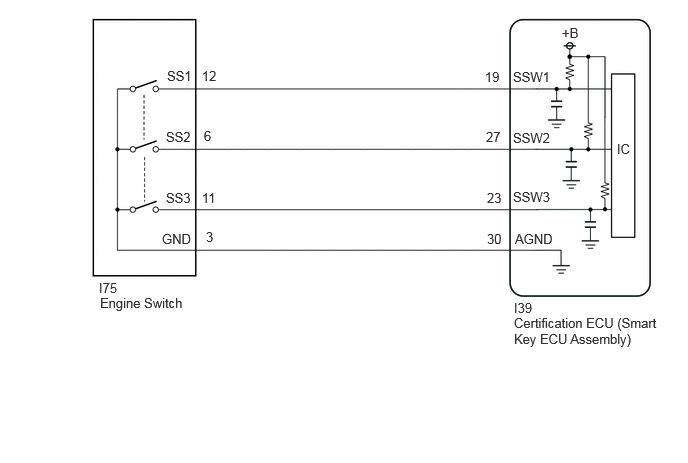
CAUTION / NOTICE / HINT
- NOTICE:
-
·
When using the GTS with the ignition switch off, connect the GTS to the DLC3 and turn a courtesy light switch on and off at intervals of 1.5 seconds or less until communication between the GTS and the vehicle begins. Then select the vehicle type under manual mode and enter the following menus: Body Electrical / Entry&Start(CAN). While using the GTS, periodically turn a courtesy light switch on and off at intervals of 1.5 seconds or less to maintain communication between the GTS and the vehicle.
·The entry and start system (for Start Function) uses the LIN communication system and CAN communication system. Inspect the communication function by following How to Proceed with Troubleshooting. Troubleshoot the entry and start system (for Start Function) after confirming that the communication systems are functioning properly.
·Before replacing the certification ECU (smart key ECU assembly), refer to Service Bulletin.
·After repair, confirm that no DTCs are output by performing "DTC Output Confirmation Operation".
PROCEDURE
Read the Data List according to the display on the GTS.
- Body Electrical > Power Source Control > Data List
-
Tester Display Measurement Item Range Normal Condition Diagnostic Note Push Start Switch 1 Engine switch 1 status OFF or ON OFF: Engine switch not pressed
ON: Engine switch pressed·If the engine switch is pressed for a short time, the display may not change.
·Use this item to determine if the engine switch input signal is malfunctioning.
Push Start Switch 2 Engine switch 2 status OFF or ON OFF: Engine switch not pressed
ON: Engine switch pressed·If the engine switch is pressed for a short time, the display may not change.
·Use this item to determine if the engine switch input signal is malfunctioning.
Push Start Switch 3 Engine switch 3 status OFF or ON OFF: Engine switch not pressed
ON: Engine switch pressed·If the engine switch is pressed for a short time, the display may not change.
·Use this item to determine if the engine switch input signal is malfunctioning.
- Body Electrical > Power Source Control > Data List
-
Tester Display Push Start Switch 1 Push Start Switch 2 Push Start Switch 3 - 50003 454 201,202,203
- OK:
-
The GTS display changes correctly in response to the engine switch operation.
- Result:
-
Proceed to OK NG
OK
NG
According to the display on the GTS, read the Data List while wiggling the wire harness.
- Body Electrical > Power Source Control > Data List
-
Tester Display Measurement Item Range Normal Condition Diagnostic Note Push Start Switch 1 Engine switch 1 status OFF or ON OFF: Engine switch not pressed
ON: Engine switch pressed·If the engine switch is pressed for a short time, the display may not change.
·Use this item to determine if the engine switch input signal is malfunctioning.
Push Start Switch 2 Engine switch 2 status OFF or ON OFF: Engine switch not pressed
ON: Engine switch pressed·If the engine switch is pressed for a short time, the display may not change.
·Use this item to determine if the engine switch input signal is malfunctioning.
Push Start Switch 3 Engine switch 3 status OFF or ON OFF: Engine switch not pressed
ON: Engine switch pressed·If the engine switch is pressed for a short time, the display may not change.
·Use this item to determine if the engine switch input signal is malfunctioning.
- Body Electrical > Power Source Control > Data List
-
Tester Display Push Start Switch 1 Push Start Switch 2 Push Start Switch 3 - 50003 454 201,202,203
- OK:
-
The GTS display changes correctly in response to the engine switch operation.
- Result:
-
Proceed to OK NG
OK
NG
Pre-procedure1
Disconnect the I39 certification ECU (smart key ECU assembly) connector.
Disconnect the I75 engine switch connector.
Procedure1
Measure the resistance according to the value(s) in the table below.
- Standard Resistance:
-
Tester Connection Condition Specified Condition Click Location & Routing(I39,I75)Location & Routingewd_type=routing;type=c,c;code=I39,I75
I39-19 (SSW1) - I75-12 (SS1) Always Below 1 Ω I39-27 (SSW2) - I75-6 (SS2) Always Below 1 Ω I39-23 (SSW3) - I75-11 (SS3) Always Below 1 Ω I39-30 (AGND) - I75-3 (GND) Always Below 1 Ω I39-19 (SSW1) or I75-12 (SS1) - Other terminals and body ground Always 10 kΩ or higher I39-27 (SSW2) or I75-6 (SS2) - Other terminals and body ground Always 10 kΩ or higher I39-23 (SSW3) or I75-11 (SS3) - Other terminals and body ground Always 10 kΩ or higher I39-30 (AGND) or I75-3 (GND) - Other terminals and body ground Always 10 kΩ or higher
- Result:
-
Proceed to OK NG
Post-procedure1
None
OK
NG
for 1GR-FE:
Click hereEngine / Hybrid System>1GR-FE (STARTING)>ENGINE SWITCH>INSPECTION
for V35A-FTS:
Click hereEngine / Hybrid System>V35A-FTS (STARTING)>ENGINE SWITCH>INSPECTION
for F33A-FTV:
Click hereEngine / Hybrid System>F33A-FTV (STARTING)>ENGINE SWITCH>INSPECTION
- Result:
-
Proceed to OK NG
OK
NG
for 1GR-FE:
Click hereEngine / Hybrid System>1GR-FE (STARTING)>ENGINE SWITCH>REMOVAL
for V35A-FTS:
Click hereEngine / Hybrid System>V35A-FTS (STARTING)>ENGINE SWITCH>REMOVAL
for F33A-FTV:
Click hereEngine / Hybrid System>F33A-FTV (STARTING)>ENGINE SWITCH>REMOVAL