REAR SUSPENSION REAR STABILIZER BAR(w/ Electronic-Kinetic Dynamic Suspension System) INSTALLATION
CAUTION / NOTICE / HINT
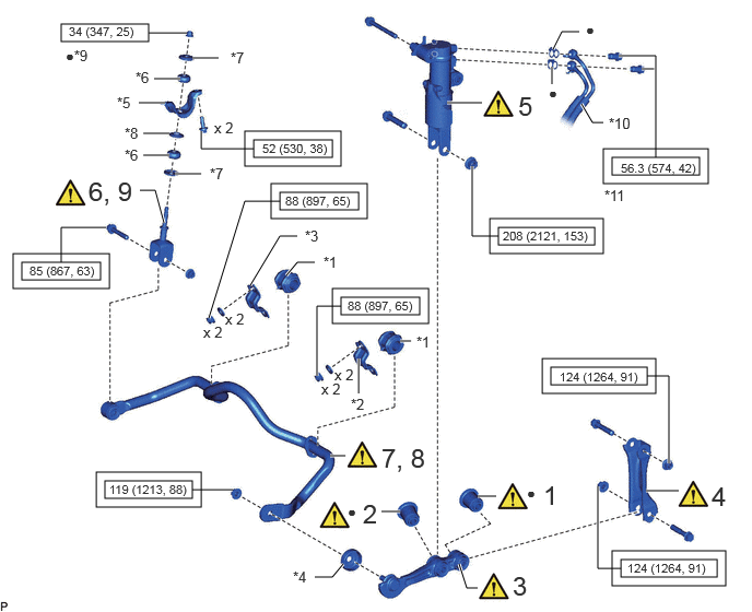
| Procedure | Part Name Code |

|

|

|
|
|---|---|---|---|---|---|
| 1 | REAR STABILIZER LINK BUSH (for Front Side) | 48849D | ( ) |
- | - |
| 2 | REAR STABILIZER LINK BUSH (for Rear Side) | 48849D | () |
- | - |
| 3 | REAR STABILIZER CONTROL ARM ASSEMBLY | 488B0 | () |
- | - |
| 4 | REAR NO. 2 STABILIZER CONTROL ARM | 488B2 | () |
- | - |
| 5 | TEMPORARILY INSTALL REAR STABILIZER CONTROL CYLINDER | 48885 | () |
- | - |
| 6 | INSTALL STABILIZER LINK SUB-ASSEMBLY | 48802 | () |
- | - |
| 7 | INSTALL REAR STABILIZER BAR SUB-ASSEMBLY | 48805 | - | - | - |
| 8 | CONNECT REAR STABILIZER BAR SUB-ASSEMBLY | 48805 | () |
- | - |
| 9 | CONNECT STABILIZER LINK SUB-ASSEMBLY | 48802 | - | - | - |
| *1 | REAR STABILIZER BUSH | *2 | REAR STABILIZER BAR BRACKET LH |
| *3 | REAR STABILIZER BAR BRACKET RH | *4 | LOWER BALL JOINT DUST COVER PROTECTOR |
| *5 | STABILIZER END BRACKET RH | *6 | REAR STABILIZER CUSHION |
| *7 | REAR NO. 1 STABILIZER BAR CUSHION RETAINER | *8 | REAR NO. 2 STABILIZER BAR CUSHION RETAINER |
| *9 | LOCK NUT | *10 | REAR STABILIZER CONTROL TUBE |
| *11 | UNION BOLT | - | - |

|
Tightening torque for "Major areas involving basic vehicle performance such as moving/turning/stopping": N*m (kgf*cm, ft.*lbf) |

|
N*m (kgf*cm, ft.*lbf): Specified torque |
| ● | Non-reusable part | - | - |
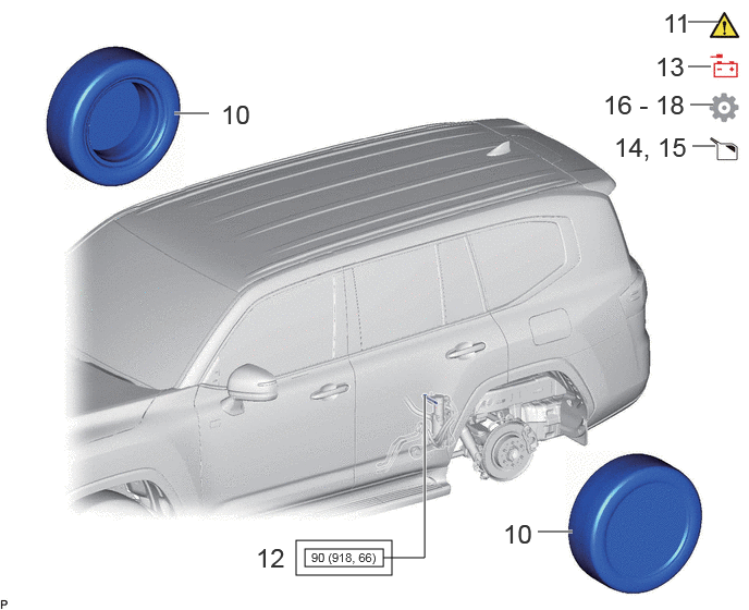
| Procedure | Part Name Code |
|
|
|
|
|---|---|---|---|---|---|
| 10 | REAR WHEEL | - | - | - | - |
| 11 | STABILIZE SUSPENSION | - | () |
- | - |
| 12 | FULLY TIGHTEN REAR STABILIZER CONTROL CYLINDER | 48885 | - | - | - |
| 13 | CONNECT CABLE TO NEGATIVE BATTERY TERMINAL | - | - | - | - |
| 14 | BLEED AIR FROM SUSPENSION FLUID | - | - | () |
- |
| 15 | APPLY PRESSURE ACCORDING TO TEMPERATURE MANAGEMENT CHART WHEN FILLING FLUID | - | - | - | - |
| 16 | INSPECT FOR SUSPENSION FLUID LEAK | - | - | - | () |
| 17 | MEASURE VEHICLE HEIGHT | - | - | - | () |
| 18 | INITIALIZATION AFTER RECONNECTING BATTERY TERMINAL | - | - | - | () |

0,0 0,0 false
|
Tightening torque for "Major areas involving basic vehicle performance such as moving/turning/stopping": N*m (kgf*cm, ft.*lbf) | - | - |
CAUTION / NOTICE / HINT
PROCEDURE

 48849D 1.INSTALL REAR STABILIZER LINK BUSH (for Front Side)
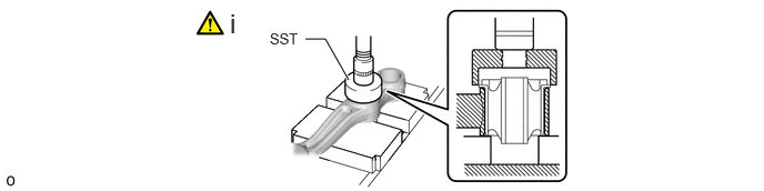
Using SST and a press, press in a new rear stabilizer link bush (front side).
- SST
-
09710-20011 (09710-06071)
48849D 2.INSTALL REAR STABILIZER LINK BUSH (for Rear Side)
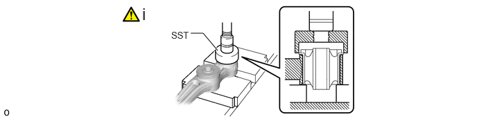
Using SST and a press, press in a new rear stabilizer link bush (rear side).
- SST
-
09710-30021 (09710-03051)
488B0 3.INSTALL REAR STABILIZER CONTROL ARM ASSEMBLY
|
|
|
- Torque:
- 208 N*m (2121 kgf*cm, 153 ft.*lbf)
488B2 4.INSTALL REAR NO. 2 STABILIZER CONTROL ARM
|
|
|
- Torque:
- 124 N*m (1264 kgf*cm, 91 ft.*lbf)
48885 5.TEMPORARILY INSTALL REAR STABILIZER CONTROL CYLINDER
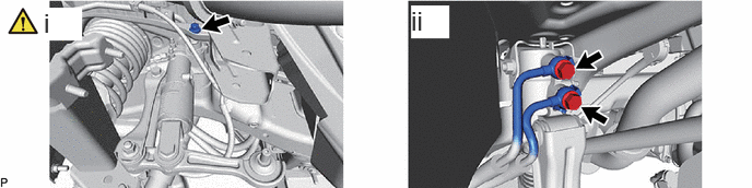
Temporarily install the rear stabilizer control cylinder to the frame with the bolt.
Install the rear stabilizer control tube and 2 new gaskets to the rear stabilizer control cylinder with the 2 union bolts.
- Torque:
- 56.3 N*m (574 kgf*cm, 42 ft.*lbf)
48802 6.INSTALL STABILIZER LINK SUB-ASSEMBLY
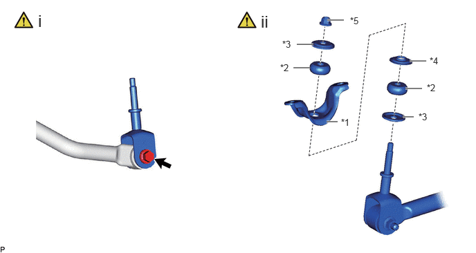
| *1 | Stabilizer End Bracket RH | *2 | Rear Stabilizer Cushion |
| *3 | Rear No. 1 Stabilizer Bar Cushion Retainer | *4 | Rear No. 2 Stabilizer Bar Cushion Retainer |
| *5 | Lock Nut | - | - |
Install the stabilizer link to the stabilizer bar with the bolt and nut.
- Torque:
- 85 N*m (867 kgf*cm, 63 ft.*lbf)
- NOTICE:
-
Make sure the bolt is facing the correct direction.
Make sure that all parts are facing as shown in the illustration and install the stabilizer end bracket RH, rear No. 1 stabilizer bar cushion retainers, rear No. 2 stabilizer bar cushion retainer and rear stabilizer cushions with a new lock nut.
- Torque:
- 34 N*m (347 kgf*cm, 25 ft.*lbf)
48805 7.INSTALL REAR STABILIZER BAR SUB-ASSEMBLY
- Torque:
- 88 N*m (897 kgf*cm, 65 ft.*lbf)
48805 8.CONNECT REAR STABILIZER BAR SUB-ASSEMBLY
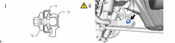
| *1 | Ball Joint Dust Cover Protector | *2 | Rear Stabilizer Bar Sub-assembly |
| *3 | Rear Stabilizer Control Arm Assembly | - | - |
Install the rear stabilizer control arm assembly to the ball joint dust cover protector.
Connect the stabilizer barrear to the stabilizer control arm assembly with the nut.
- Torque:
- 119 N*m (1213 kgf*cm, 88 ft.*lbf)
- HINT:
-
·
If the ball joint turns together with the nut, use a 6 mm hexagon wrench to hold the stud bolt.
·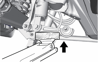
If the rear stabilizer control cylinder extends and it is difficult to temporarily install the stabilizer link to the stabilizer bar, raise the stabilizer control arm with a jack and temporarily install the stabilizer link.
48802 9.CONNECT STABILIZER LINK SUB-ASSEMBLY
- Torque:
- 52 N*m (530 kgf*cm, 38 ft.*lbf)
10.INSTALL REAR WHEEL
11.STABILIZE SUSPENSION
|
|
Click here() |
48885 12.FULLY TIGHTEN REAR STABILIZER CONTROL CYLINDER
- Torque:
- 90 N*m (918 kgf*cm, 66 ft.*lbf)
13.CONNECT CABLE TO NEGATIVE BATTERY TERMINAL
for F33A-FTV:
for V35A-FTS:
14.BLEED AIR FROM SUSPENSION FLUID
|
|
Click here() |
15.APPLY PRESSURE ACCORDING TO TEMPERATURE MANAGEMENT CHART WHEN FILLING FLUID
16.INSPECT FOR SUSPENSION FLUID LEAK
|
|
Click here() |
17.MEASURE VEHICLE HEIGHT
|
|
Click here() |
18. INITIALIZATION AFTER RECONNECTING BATTERY TERMINAL
Click hereGeneral>SETUP>WHEN DISCONNECTING OR RECONNECTING BATTERY TERMINAL>WORK PROCEDURE
- HINT:
-
When disconnecting and reconnecting the battery ,there is an automatic learning function that completes learning when the respective system is used.
-
Click hereGeneral>SETUP>WHEN DISCONNECTING OR RECONNECTING BATTERY TERMINAL>AUTOMATIC LEARNING CHART