POWER ASSIST SYSTEMS VANE PUMP(for F33A-FTV) INSTALLATION
CAUTION / NOTICE / HINT
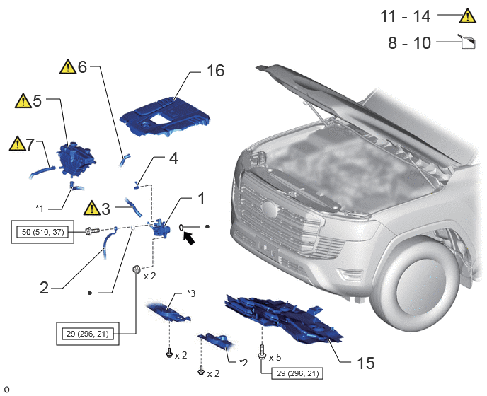
| Procedure | Part Name Code |

|

|

|
|
|---|---|---|---|---|---|
| 1 | VANE PUMP ASSEMBLY | 44310 | - | - | - |
| 2 | PRESSURE FEED TUBE ASSEMBLY | 44410 | - | - | - |
| 3 | NO. 1 OIL RESERVOIR TO PUMP HOSE | 44348A | ( ) |
- | - |
| 4 | SOLENOID VALVE CONNECTOR | - | - | - | - |
| 5 | RESERVE SEALED WITHOUT CAP TANK | 164A2 | () |
- | - |
| 6 | NO. 3 WATER BY-PASS HOSE | 16267 | () |
- | - |
| 7 | WATER BY-PASS HOSE | 16261 | () |
- | - |
| 8 | ADD POWER STEERING FLUID | - | - | - | - |
| 9 | ADD ENGINE COOLANT | - | - | () |
- |
| 10 | DD COOLANT (for Intercooler) | - | - | () |
- |
| 11 | BLEED POWER STEERING FLUID | - | - | - | - |
| 12 | CHECK FOR POWER STEERING FLUID LEAKAGE | - | - | - | - |
| 13 | INSPECT FOR COOLANT LEAK | - | () |
- | - |
| 14 | INSPECT FOR COOLANT LEAK (for Intercooler) | - | () |
- | - |
| 15 | NO. 1 ENGINE UNDER COVER ASSEMBLY | 51410 | - | - | - |
| 16 | NO. 1 ENGINE COVER SUB-ASSEMBLY | 12601B | - | - | - |
| *1 | NO. 2 WATER BY-PASS HOSE | - | ENGINE SIDE COVER SUB-ASSEMBLY LH |
| *3 | ENGINE SIDE COVER SUB-ASSEMBLY RH | - | - |

|
Tightening torque for "Major areas involving basic vehicle performance such as moving/turning/stopping": N*m (kgf*cm, ft.*lbf) |

|
N*m (kgf*cm, ft.*lbf): Specified torque |
| ● | Non-reusable part | - | - |
CAUTION / NOTICE / HINT
- HINT:
-
·
Use the same procedure for RHD and LHD vehicles.
·The procedure listed below is for LHD vehicles.
PROCEDURE

 44310 1.INSTALL VANE PUMP ASSEMBLY
- Torque:
- 29 N*m (296 kgf*cm, 21 ft.*lbf)
44410 2.CONNECT PRESSURE FEED TUBE ASSEMBLY
- Torque:
- 50 N*m (510 kgf*cm, 37 ft.*lbf)
44348A 3.CONNECT NO. 1 OIL RESERVOIR TO PUMP HOSE
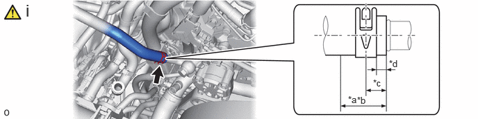
| *a | Clip Positioning Area | *b | 29 mm (1.14 in.) |
| *c | 12 mm (0.472 in.) | *d | 3 to 9 mm (0.118 to 0.354 in.) |
Connect the No. 1 oil reservoir to pump hose to the vane pump assembly and slide the hose clip to secure it.
- NOTICE:
-
Align the hose and the hose clip at the locations shown in the illustration and install them.
4.CONNECT SOLENOID VALVE CONNECTOR
164A2 5.CONNECT RADIATOR RESERVE TANK ASSEMBLY
|
|
Click here() |
16267 6.CONNECT NO. 3 WATER BY-PASS HOSE
|
|
Click here() |
16261 7.CONNECT WATER BY-PASS HOSE
|
|
Click here() |
8.ADD POWER STEERING FLUID
9.ADD ENGINE COOLANT
|
|
Click here() |
10.ADD COOLANT (for Intercooler)
|
|
Click here() |
11.BLEED POWER STEERING FLUID
12.CHECK FOR POWER STEERING FLUID LEAKAGE
13.INSPECT FOR COOLANT LEAK
|
|
Click here() |
14.INSPECT FOR COOLANT LEAK (for Intercooler)
|
|
Click here() |
51410 15.INSTALL NO. 1 ENGINE UNDER COVER ASSEMBLY
12601B 16.INSTALL NO. 1 ENGINE COVER SUB-ASSEMBLY