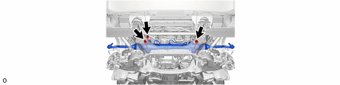
STEERING GEAR / LINKAGE STEERING GEAR REMOVAL
CAUTION / NOTICE / HINT
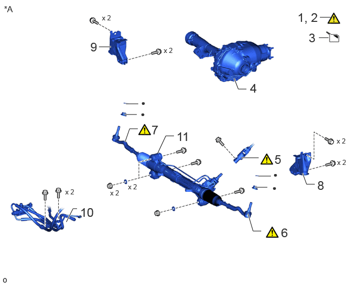
| Procedure | Part Name Code |

|

|

|
|
|---|---|---|---|---|---|
| 1 | ALIGN FRONT WHEELS FACING STRAIGHT AHEAD | - | - | - | - |
| 2 | SECURE STEERING WHEEL | - | ( ) |
- | - |
| 3 | DRAIN POWER STEERING FLUID | - | - | - | - |
| 4 | FRONT DIFFERENTIAL CARRIER ASSEMBLY | 41110F | - | - | - |
| 5 | NO. 2 STEERING INTERMEDIATE SHAFT SUB-ASSEMBLY | 45203 | () |
- | - |
| 6 | TIE ROD END SUB-ASSEMBLY LH | 45047 | () |
- | - |
| 7 | TIE ROD END SUB-ASSEMBLY RH | 45046 | () |
- | - |
| 8 | FRONT BOUND STOPPER BRACKET SUB-ASSEMBLY LH | 51604 | - | - | - |
| 9 | FRONT BOUND STOPPER BRACKET SUB-ASSEMBLY RH | 51603A | - | - | - |
| 10 | PRESSURE FEED TUBE ASSEMBLY | - | - | - | - |
| 11 | RACK AND PINION POWER STEERING GEAR ASSEMBLY | 44250 | - | - | - |
| *A | for V35A-FTS | - | - |
| ● | Non-reusable part | - | - |
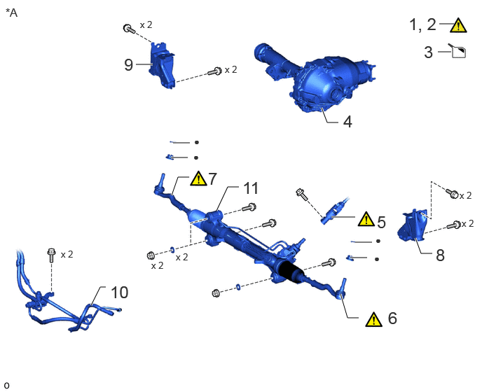
| Procedure | Part Name Code |
|
|
|
|
|---|---|---|---|---|---|
| 1 | ALIGN FRONT WHEELS FACING STRAIGHT AHEAD | - | - | - | - |
| 2 | SECURE STEERING WHEEL | - | () |
- | - |
| 3 | DRAIN POWER STEERING FLUID | - | - | - | - |
| 4 | FRONT DIFFERENTIAL CARRIER ASSEMBLY | 41110F | - | - | - |
| 5 | NO. 2 STEERING INTERMEDIATE SHAFT SUB-ASSEMBLY | 45203 | () |
- | - |
| 6 | TIE ROD END SUB-ASSEMBLY LH | 45047 | () |
- | - |
| 7 | TIE ROD END SUB-ASSEMBLY RH | 45046 | () |
- | - |
| 8 | FRONT BOUND STOPPER BRACKET SUB-ASSEMBLY LH | 51604 | - | - | - |
| 9 | FRONT BOUND STOPPER BRACKET SUB-ASSEMBLY RH | 51603A | - | - | - |
| 10 | PRESSURE FEED TUBE ASSEMBLY | - | - | - | - |
| 11 | RACK AND PINION POWER STEERING GEAR ASSEMBLY | 44250 | - | - | - |
| *A | for 1GR-FE | - | - |
| ● | Non-reusable part | - | - |
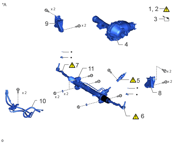
| Procedure | Part Name Code |
|
|
|
|
|---|---|---|---|---|---|
| 1 | ALIGN FRONT WHEELS FACING STRAIGHT AHEAD | - | - | - | - |
| 2 | SECURE STEERING WHEEL | - | () |
- | - |
| 3 | DRAIN POWER STEERING FLUID | - | - | - | - |
| 4 | FRONT DIFFERENTIAL CARRIER ASSEMBLY | 41110F | - | - | - |
| 5 | NO. 2 STEERING INTERMEDIATE SHAFT SUB-ASSEMBLY | 45203 | () |
- | - |
| 6 | TIE ROD END SUB-ASSEMBLY LH | 45047 | () |
- | - |
| 7 | TIE ROD END SUB-ASSEMBLY RH | 45046 | () |
- | - |
| 8 | FRONT BOUND STOPPER BRACKET SUB-ASSEMBLY LH | 51604 | - | - | - |
| 9 | FRONT BOUND STOPPER BRACKET SUB-ASSEMBLY RH | 51603A | - | - | - |
| 10 | PRESSURE FEED TUBE ASSEMBLY | - | - | - | - |
| 11 | RACK AND PINION POWER STEERING GEAR ASSEMBLY | 44250 | - | - | - |
| *A | for F33A-FTV | - | - |
| ● | Non-reusable part | - | - |
CAUTION / NOTICE / HINT
The necessary procedures (adjustment, calibration, initialization, or registration) that must be performed after parts are removed, installed, or replaced during the rack and pinion power steering gear assembly removal/installation are shown below.
- Necessary Procedure After Parts Removed/Installed/Replaced:
-
Replacement Part or Procedure Necessary Procedures Effects/Inoperative when not Performed Link Wheel alignment adjustment Perform "Calibration" ·DTCs are stored
·ABS warning light illuminates
·Brake system warning light (yellow indicator) illuminates
·Slip indicator light illuminates
·Electronically controlled brake system does not operate correctly
( )Disconnect cable from negative auxiliary battery terminal Memorize steering angle neutral point Parking assist monitor system ( )Multi-terrain monitor system ( )Panoramic view monitor system ( )
- HINT:
-
When the cable is disconnected/reconnected to the auxiliary battery terminal, systems temporarily stop operating. However, each system has a function that completes learning the first time the system is used.
-
·
Learning completes when vehicle is driven
Effect/Inoperative Function When Necessary Procedures are not Performed Necessary Procedures Link Stop and start system Drive the vehicle until stop and start control is permitted (approximately 5 to 60 minutes). ( )Lighting system (EXT) Cornering lights Drive the vehicle straight ahead at 35 km/h (22 mph) or more for 5 seconds or more. ( )Pre-collision system Lane tracing assist system Lane departure alert system Adaptive high beam system
·Learning completes when vehicle is operated normally
Effect/Inoperative Function When Necessary Procedures are not Performed Necessary Procedures Link Power back door system Fully close the back door by hand.
- HINT:
-
Initialization is not necessary if the above procedures are performed while the back door is closed.
( )Air conditioning system After the ignition switch is turned to ON, theservo motor and expansion valve standardposition is recognized. -
·Use the same procedure for RHD and LHD vehicles.
·The procedure listed below is for LHD vehicles.
PROCEDURE

 1.ALIGN FRONT WHEELS FACING STRAIGHT AHEAD
2. SECURE STEERING WHEEL
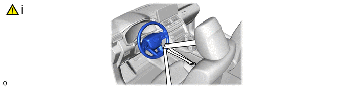
Secure the steering wheel with the seat belt in order to prevent rotation.
- HINT:
-
This operation is useful to prevent damage to the spiral cable.
3.DRAIN POWER STEERING FLUID
41110F 4.REMOVE FRONT DIFFERENTIAL CARRIER ASSEMBLY
w/ Differential Lock:
Click hereDrivetrain>AXLE AND DIFFERENTIAL>FRONT DIFFERENTIAL CARRIER ASSEMBLY (w/ Differential Lock)>REMOVAL
w/o Differential Lock:
Click hereDrivetrain>AXLE AND DIFFERENTIAL>FRONT DIFFERENTIAL CARRIER ASSEMBLY (w/o Differential Lock)>REMOVAL
45203 5.DISCONNECT NO. 2 STEERING INTERMEDIATE SHAFT SUB-ASSEMBLY
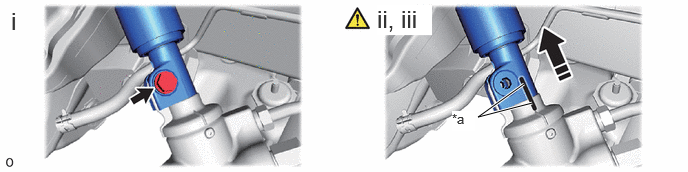
| *a | Matchmark | - | - |

|
Slide | - | - |
Remove the bolt.
Slide the No. 2 steering intermediate shaft sub-assembly and put matchmarks on the No. 2 steering intermediate shaft sub-assembly and the rack and pinion power steering gear assembly.
Disconnect the No. 2 steering intermediate shaft sub-assembly from the rack and pinion power steering gear assembly.
45047 6.DISCONNECT TIE ROD END SUB-ASSEMBLY LH
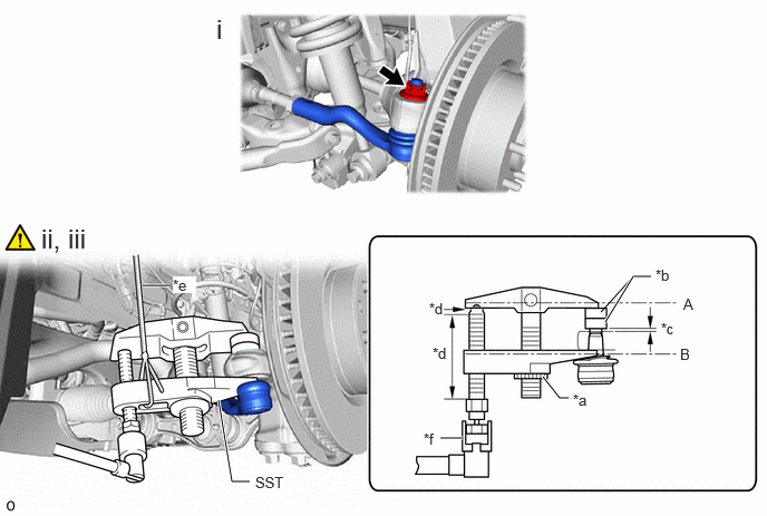
| *a | Center Nut | *b | SST (Spacer B) |
| *c | 1 mm (0.0394 in.) | *d | Molybdenum grease application area |
| *e | String | *f | Place wrench here |
Remove the clip and nut.
Install 2 spacers (SST spacer B) to the steering knuckle LH as shown in the illustration.
- SST
-
09960-20010 (09961-02060)
- NOTICE:
-
Make sure that the clearance between the tie rod assembly LH and spacers (SST spacer B) is 1 mm (0.0394 in.) or more to prevent damage to SST.
Using SST, disconnect the tie rod end sub-assembly LH from the steering knuckle LH.
- SST
-
09960-20010 (09961-02010)
- CAUTION:
-
Apply molybdenum grease to the bolt threads and the tip of SST.
- NOTICE:
-
·
Be sure to tighten the string firmly to secure SST to the steering knuckle to prevent SST from falling off.
·Install SST so that (A) and (B) shown in the illustration are parallel. Otherwise, the ball joint dust cover may be damaged.
·Be sure to place the wrench on the part shown in the illustration.
·Do not damage the ball joint dust cover.
·Do not damage the steering knuckle.
·Do not damage the front disc brake dust cover.
45046 7.DISCONNECT TIE ROD END SUB-ASSEMBLY RH
Perform the same procedure as for the LH side.
51604 8.REMOVE FRONT BOUND STOPPER BRACKET SUB-ASSEMBLY LH
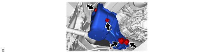
51603A 9.REMOVE FRONT BOUND STOPPER BRACKET SUB-ASSEMBLY RH
Perform the same procedure as for the LH side.
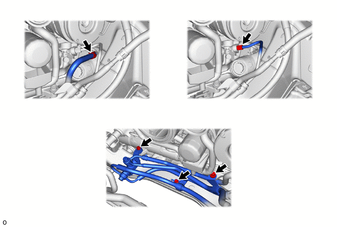
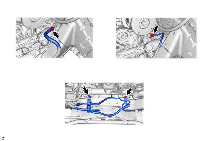
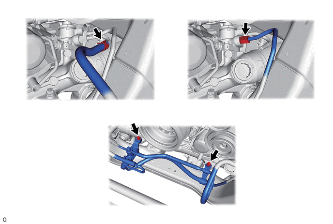
10.DISCONNECT PRESSURE FEED TUBE ASSEMBLY
for V35A-FTS:
for 1GR-FE:
for F33A-FTV:
44250 11.REMOVE RACK AND PINION POWER STEERING GEAR ASSEMBLY