Home › Audio / Visual / Telematics › AUDIO / VIDEO › AUDIO AND VISUAL SYSTEM (for Radio and Display Type, except 12.3 Inch Display) › from 2021.07
RM38G0E _56 Audio / Visual / Telematics _100606 AUDIO / VIDEO _0467497 AUDIO AND VISUAL SYSTEM(for Radio and Display Type, except 12.3 Inch Display) C

AUDIO / VIDEO  AUDIO AND VISUAL SYSTEM(for Radio and Display Type, except 12.3 Inch Display)  B15C3  Speaker Output Short  


DESCRIPTION

This DTC is stored when a malfunction occurs in the speakers.

DTC No. Detection Item DTC Detection Condition Trouble Area DTC Output from Priority
B15C3 Speaker Output Short A short is detected in the speaker output circuit
·

Harness or connector

·

Speaker

·

Radio and display receiver assembly

·

Stereo component equalizer assembly*1

·

Telephone transceiver assembly*2


Navigation System A

*1: w/ Active Noise Control System

*2: w/ Telematics Transceiver (for Toyota Connected Services)


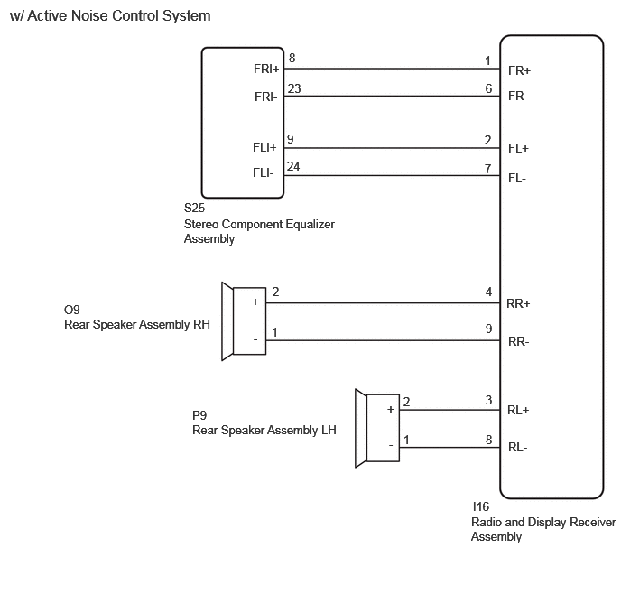
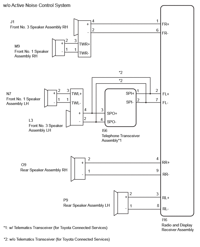
WIRING DIAGRAM
E473836E01
5.802,0.781 6.354,1.042 0.552,0.26 10 false FR+ 5.802,1.104 6.354,1.365 0.552,0.26 10 false FR- 0.521,1.76 1.802,2.229 1.281,0.469 10 false Front No. 1 Speaker Assembly RH 0.365,0.885 2.583,1.073 2.219,0.188 10 false Front No. 3 Speaker Assembly RH 0.229,3.469 1.51,3.938 1.281,0.469 10 false Front No. 1 Speaker Assembly LH 1.031,4.427 2.302,5 1.271,0.573 10 false Front No. 3 Speaker Assembly LH 0.729,6.021 2.896,6.354 2.167,0.333 10 false Rear Speaker Assembly RH 2.271,7.292 4.438,7.625 2.167,0.333 10 false Rear Speaker Assembly LH 5.792,8 7.01,8.531 1.219,0.531 10 false Radio and Display Receiver Assembly 5.823,3.292 6.375,3.552 0.552,0.26 10 false FL+ 5.823,3.604 6.375,3.865 0.552,0.26 10 false FL- 2.563,3.281 3.115,3.542 0.552,0.26 10 false TWL+ 2.563,3.615 3.115,3.875 0.552,0.26 10 false TWL- 2.813,3.979 3.365,4.24 0.552,0.26 10 false + 2.833,4.271 3.385,4.531 0.552,0.26 10 false - 1.927,3.594 2.479,3.854 0.552,0.26 10 false - 1.906,3.26 2.458,3.521 0.552,0.26 10 false + 3.104,0.781 3.656,1.042 0.552,0.26 10 false + 3.135,1.073 3.688,1.333 0.552,0.26 10 false - 2.833,1.5 3.385,1.76 0.552,0.26 10 false TWR+ 2.833,1.823 3.385,2.083 0.552,0.26 10 false TWR- 5.802,5.75 6.354,6.01 0.552,0.26 10 false RR+ 5.823,6.177 6.375,6.438 0.552,0.26 10 false RR- 2.917,5.76 3.469,6.021 0.552,0.26 10 false + 2.938,6.177 3.49,6.438 0.552,0.26 10 false - 5.813,7.021 6.365,7.281 0.552,0.26 10 false RL+ 5.823,7.417 6.375,7.677 0.552,0.26 10 false RL- 4.479,6.99 5.031,7.25 0.552,0.26 10 false + 4.49,7.396 5.042,7.656 0.552,0.26 10 false - 5.802,7.813 6.354,8.073 0.552,0.26 10 false I16 5.604,0.667 6.156,0.927 0.552,0.26 10 false 1 5.604,1 6.156,1.26 0.552,0.26 10 false 6 5.583,3.167 6.135,3.427 0.552,0.26 10 false 2 5.583,3.5 6.135,3.76 0.552,0.26 10 false 7 5.604,5.615 6.156,5.875 0.552,0.26 10 false 4 5.604,6.042 6.156,6.302 0.552,0.26 10 false 9 5.604,6.885 6.156,7.146 0.552,0.26 10 false 3 5.625,7.302 6.177,7.563 0.552,0.26 10 false 8 0.375,0.698 0.927,0.958 0.552,0.26 10 false J1 1.031,4.24 1.583,4.5 0.552,0.26 10 false L3 3.302,0.667 3.854,0.927 0.552,0.26 10 false 4 3.302,0.99 3.854,1.25 0.552,0.26 10 false 2 2.396,3.167 2.948,3.427 0.552,0.26 10 false 3 2.667,1.698 3.219,1.958 0.552,0.26 10 false 1 2.354,1.688 2.906,1.948 0.552,0.26 10 false 1 2.354,1.365 2.906,1.625 0.552,0.26 10 false 2 0.521,1.573 1.073,1.833 0.552,0.26 10 false M9 0.229,3.281 0.781,3.542 0.552,0.26 10 false N7 3.021,3.854 3.25,4.177 0.229,0.323 10 false 4 3.01,4.177 3.563,4.438 0.552,0.26 10 false 2 2.385,3.49 2.938,3.75 0.552,0.26 10 false 1 2.667,1.375 3.219,1.635 0.552,0.26 10 false 3 2.083,3.167 2.635,3.427 0.552,0.26 10 false 2 2.073,3.49 2.625,3.75 0.552,0.26 10 false 1 3.156,6.063 3.708,6.323 0.552,0.26 10 false 1 3.156,5.625 3.708,5.885 0.552,0.26 10 false 2 4.656,7.313 5.208,7.573 0.552,0.26 10 false 1 4.646,6.875 5.198,7.135 0.552,0.26 10 false 2 0.76,5.833 1.313,6.094 0.552,0.26 10 false O9 2.271,7.104 2.823,7.365 0.552,0.26 10 false P9 2.188,1.469 2.74,1.729 0.552,0.26 10 false + 2.208,1.76 2.76,2.021 0.552,0.26 10 false - 0.115,0.083 4.99,0.458 4.875,0.375 12 false w/o Active Noise Control System 3.833,3.99 4.385,4.25 0.552,0.26 10 false SPO+ 3.833,4.292 4.385,4.552 0.552,0.26 10 false SPO- 3.625,3.865 4.177,4.125 0.552,0.26 10 false 3 3.604,4.208 3.833,4.531 0.229,0.323 10 false 4 4.51,3.271 5.063,3.531 0.552,0.26 10 false SPI+ 4.521,3.583 5.073,3.844 0.552,0.26 10 false SPI- 4.917,3.51 5.469,3.771 0.552,0.26 10 false 2 4.906,3.177 5.458,3.438 0.552,0.26 10 false 1 3.656,4.604 4.208,4.865 0.552,0.26 10 false I56 3.646,4.792 5.031,5.188 1.385,0.396 10 false Telephone Transceiver Assembly*1 4.26,2.521 4.813,2.781 0.552,0.26 10 false *2 4.26,2.813 4.813,3.073 0.552,0.26 10 false *2 0.135,8.51 4.094,8.823 3.958,0.313 10 false *2: w/o Telematics Transceiver (for Toyota Connected Services) 0.125,8.094 4.083,8.406 3.958,0.313 10 false *1: w/ Telematics Transceiver (for Toyota Connected Services)

E464174E01
5.438,5.938 7.146,6.542 1.708,0.604 10 false Radio and Display Receiver Assembly 2.219,4.875 4.125,5.323 1.906,0.448 10 false Rear Speaker Assembly LH 0.74,3.656 2.646,4.104 1.906,0.448 10 false Rear Speaker Assembly RH 5.844,3.417 6.271,3.646 0.427,0.229 10 false RR+ 5.865,3.854 6.292,4.083 0.427,0.229 10 false RR- 5.865,5.073 6.292,5.302 0.427,0.229 10 false RL- 5.854,4.646 6.281,4.875 0.427,0.229 10 false RL+ 5.865,0.729 6.292,0.958 0.427,0.229 10 false FR+ 5.865,1.021 6.292,1.25 0.427,0.229 10 false FR- 5.865,1.969 6.292,2.198 0.427,0.229 10 false FL- 5.865,1.625 6.292,1.854 0.427,0.229 10 false FL+ 5.604,3.281 5.813,3.469 0.208,0.188 10 false 4 5.604,3.708 5.813,3.896 0.208,0.188 10 false 9 5.604,4.531 5.813,4.719 0.208,0.188 10 false 3 5.604,4.99 5.813,5.177 0.208,0.188 10 false 8 2.125,2.313 2.552,2.542 0.427,0.229 10 false S25 2.125,2.5 3.906,2.948 1.781,0.448 10 false Stereo Component Equalizer Assembly 2.927,0.708 3.354,0.938 0.427,0.229 10 false FRI+ 2.938,1.031 3.365,1.26 0.427,0.229 10 false FRI- 2.917,1.906 3.344,2.135 0.427,0.229 10 false FLI- 2.917,1.615 3.344,1.844 0.427,0.229 10 false FLI+ 5.594,0.615 5.75,0.823 0.156,0.208 10 false 1 5.604,0.938 5.76,1.146 0.156,0.208 10 false 6 5.594,1.531 5.75,1.74 0.156,0.208 10 false 2 5.594,1.865 5.75,2.073 0.156,0.208 10 false 7 3.323,0.938 3.563,1.146 0.24,0.208 10 false 23 3.333,0.583 3.49,0.792 0.156,0.208 10 false 8 3.313,1.833 3.552,2.042 0.24,0.208 10 false 24 3.313,1.521 3.552,1.729 0.24,0.208 10 false 9 0.74,3.49 1.167,3.719 0.427,0.229 10 false O9 2.219,4.708 2.646,4.938 0.427,0.229 10 false P9 3.135,3.75 3.292,3.958 0.156,0.208 10 false 1 3.146,3.281 3.302,3.49 0.156,0.208 10 false 2 4.656,4.552 4.813,4.76 0.156,0.208 10 false 2 4.656,4.99 4.813,5.198 0.156,0.208 10 false 1 4.469,4.635 4.625,4.844 0.156,0.208 10 false + 2.906,3.396 3.063,3.604 0.156,0.208 10 false + 2.927,3.823 3.083,4.031 0.156,0.208 10 false - 4.49,5.042 4.646,5.25 0.156,0.208 10 false - 0.115,0.073 3.417,0.344 3.302,0.271 12 false w/ Active Noise Control System 5.458,5.76 5.885,5.99 0.427,0.229 10 false I16


CAUTION / NOTICE / HINT

HINT:

Depending on the parts that are replaced during vehicle inspection or maintenance, performing initialization, registration or calibration may be needed. Refer to Precaution for Audio and Visual System.

Click hereAudio / Visual / Telematics>AUDIO / VIDEO>AUDIO AND VISUAL SYSTEM (for Radio and Display Type, except 12.3 Inch Display)>PRECAUTION


PROCEDURE

1.CHECK DTC

Pre-procedure1


Procedure1

b.

Recheck for DTCs and check that no DTCs are output.

Click hereAudio / Visual / Telematics>AUDIO / VIDEO>AUDIO AND VISUAL SYSTEM (for Radio and Display Type, except 12.3 Inch Display)>DTC CHECK / CLEAR

Body Electrical > Navigation System > Trouble Codes
50001 212

Result:
Result Proceed to
DTCs are not output A
DTCs are output B


Post-procedure1

c.

None


A

B

2.CHECK MODEL
2.CHECK MODEL
a.

Choose the model to be inspected.


Result:
Result Proceed to
w/ Active Noise Control System A
w/o Active Noise Control System B


A

3.CHECK HARNESS AND CONNECTOR (SPEAKER CIRCUIT)

B

6.CHECK HARNESS AND CONNECTOR (SPEAKER CIRCUIT)
3.CHECK HARNESS AND CONNECTOR (SPEAKER CIRCUIT)

Pre-procedure1

a.

Disconnect the I16 radio and display receiver assembly connector.


b.

Disconnect the S25 stereo component equalizer assembly connector.


c.

Disconnect the O9 and P9 rear speaker assembly connectors.


Procedure1

d.

Measure the resistance according to the value(s) in the table below.

Standard Resistance:
Tester Connection Condition Specified Condition

Click Location & Routing(I16,S25,O9,P9)Location & Routing

Click Connector(I16)Instrument Panel>Instrument Panel Wire / Mobile Wireless Charger Cord / No. 1 Navigation Wire / No. 2 Instrument Panel Wire / No. 5 Instrument Panel Wire / Telephone Computer Wire>Radio & Display Receiver Assembly

Click Connector(S25)Body>No. 2 Floor Wire / Step Rear Floor Wire LH>Stereo Component Equalizer Assembly

Click Connector(O9)Body>No. 1 Rear Door Wire>Rear Speaker Assembly RH

Click Connector(P9)Body>No. 2 Rear Door Wire>Rear Speaker Assembly LH

I16-1 (FR+) - S25-8 (FRI+) Always Below 1 Ω
I16-6 (FR-) - S25-23 (FRI-) Always Below 1 Ω
I16-2 (FL+) - S25-9 (FLI+) Always Below 1 Ω
I16-7 (FL-) - S25-24 (FLI-) Always Below 1 Ω
I16-4 (RR+) - O9-2 (+) Always Below 1 Ω
I16-9 (RR-) - O9-1 (-) Always Below 1 Ω
I16-3 (RL+) - P9-2 (+) Always Below 1 Ω
I16-8 (RL-) - P9-1 (-) Always Below 1 Ω
I16-1 (FR+) - Body ground Always 10 kΩ or higher
I16-6 (FR-) - Body ground Always 10 kΩ or higher
I16-2 (FL+) - Body ground Always 10 kΩ or higher
I16-7 (FL-) - Body ground Always 10 kΩ or higher
I16-4 (RR+) - Body ground Always 10 kΩ or higher
I16-9 (RR-) - Body ground Always 10 kΩ or higher
I16-3 (RL+) - Body ground Always 10 kΩ or higher
I16-8 (RL-) - Body ground Always 10 kΩ or higher


Result:
Proceed to
OK
NG


Post-procedure1

e.

None


OK

4.INSPECT REAR SPEAKER ASSEMBLY

NG

REPAIR OR REPLACE HARNESS OR CONNECTOR

4.INSPECT REAR SPEAKER ASSEMBLY

OK

5.CHECK STEREO COMPONENT EQUALIZER ASSEMBLY

NG

5.CHECK STEREO COMPONENT EQUALIZER ASSEMBLY

Pre-procedure1

a.

Replace the stereo component equalizer assembly.

HINT:

Click hereAudio / Visual / Telematics>AUDIO / VIDEO>ACTIVE NOISE CONTROL ECU>REMOVAL


b.

Clear the DTCs.

HINT:

Click hereAudio / Visual / Telematics>AUDIO / VIDEO>AUDIO AND VISUAL SYSTEM (for Radio and Display Type, except 12.3 Inch Display)>DTC CHECK / CLEAR


Body Electrical > Navigation System > Clear DTCs
50002 212

Procedure1

c.

Recheck for DTCs and check that no DTCs are output.

HINT:

Click hereAudio / Visual / Telematics>AUDIO / VIDEO>AUDIO AND VISUAL SYSTEM (for Radio and Display Type, except 12.3 Inch Display)>DTC CHECK / CLEAR


Body Electrical > Navigation System > Trouble Codes
50001 212

Result:
Result Proceed to
DTCs are not output A
DTCs are output B


Post-procedure1

d.

None


A

END (STEREO COMPONENT EQUALIZER ASSEMBLY IS DEFECTIVE)

B

6.CHECK HARNESS AND CONNECTOR (SPEAKER CIRCUIT)

Pre-procedure1

a.

Disconnect the I16 radio and display receiver assembly connector.


b.

Disconnect the M9 and N7 front No. 1 speaker assembly connectors.


c.

Disconnect the J1 and L3 front No. 3 speaker assembly connectors.


d.

Disconnect the O9 and P9 rear speaker assembly connectors.


e.

Disconnect the I56 telematics transceiver connectors.*

*: w/ Telematics Transceiver (for Toyota Connected Services)


Procedure1

f.

Measure the resistance according to the value(s) in the table below.

Standard Resistance:
Tester Connection Condition Specified Condition

*1: w/o Telematics Transceiver (for Toyota Connected Services)

*2: w/ Telematics Transceiver (for Toyota Connected Services)

Click Location & Routing(I16,J1,L3,I56,M9,N7,O9,P9)Location & Routing

Click Connector(I16)Instrument Panel>Instrument Panel Wire / Mobile Wireless Charger Cord / No. 1 Navigation Wire / No. 2 Instrument Panel Wire / No. 5 Instrument Panel Wire / Telephone Computer Wire>Radio & Display Receiver Assembly

Click Connector(J1)Instrument Panel>No. 2 Instrument Panel Wire>Front No. 2 Speaker Assembly RH

Click Connector(L3)Instrument Panel>No. 4 Instrument Panel Wire>Front No. 2 Speaker Assembly LH

Click Connector(I56)Instrument Panel>Instrument Panel Wire / Mobile Wireless Charger Cord / No. 1 Navigation Wire / No. 2 Instrument Panel Wire / No. 5 Instrument Panel Wire / Telephone Computer Wire>Telematics Transceiver Assembly

Click Connector(M9)Body>Front Door Wire RH>Front No. 1 Speaker Assembly RH

Click Connector(N7)Body>Front Door Wire LH>Front No. 1 Speaker Assembly LH

Click Connector(O9)Body>No. 1 Rear Door Wire>Rear Speaker Assembly RH

Click Connector(P9)Body>No. 2 Rear Door Wire>Rear Speaker Assembly LH

I16-1 (FR+) - J1-4 (+) Always Below 1 Ω
I16-6 (FR-) - J1-2 (-) Always Below 1 Ω
I16-2 (FL+) - L3-4 (+)*1 Always Below 1 Ω
I16-7 (FL-) - L3-2 (-)*1 Always Below 1 Ω
I16-2 (FL+) - I56-1 (SPI+)*2 Always Below 1 Ω
I16-7 (FL-) - I56-2 (SPI-)*2 Always Below 1 Ω
I56-3 (SPO+) - L3-4 (+)*2 Always Below 1 Ω
I56-4 (SPO-) - L3-2 (-)*2 Always Below 1 Ω
J1-3 (TWR+) - M9-2 (+) Always Below 1 Ω
J1-1 (TWR-) - M9-1 (-) Always Below 1 Ω
L3-3 (TWL+) - N7-2 (+) Always Below 1 Ω
L3-1 (TWL-) - N7-1 (-) Always Below 1 Ω
I16-4 (RR+) - O9-2 (+) Always Below 1 Ω
I16-9 (RR-) - O9-1 (-) Always Below 1 Ω
I16-3 (RL+) - P9-2 (+) Always Below 1 Ω
I16-8 (RL-) - P9-1 (-) Always Below 1 Ω
I16-1 (FR+) - Body ground Always 10 kΩ or higher
I16-6 (FR-) - Body ground Always 10 kΩ or higher
I16-2 (FL+) - Body ground Always 10 kΩ or higher
I16-7 (FL-) - Body ground Always 10 kΩ or higher
J1-3 (TWR+) - Body ground Always 10 kΩ or higher
J1-1 (TWR-) - Body ground Always 10 kΩ or higher
L3-3 (TWL+) - Body ground Always 10 kΩ or higher
L3-1 (TWL-) - Body ground Always 10 kΩ or higher
I16-4 (RR+) - Body ground Always 10 kΩ or higher
I16-9 (RR-) - Body ground Always 10 kΩ or higher
I16-3 (RL+) - Body ground Always 10 kΩ or higher
I16-8 (RL-) - Body ground Always 10 kΩ or higher


Result:
Proceed to
OK
NG


Post-procedure1

g.

None


OK

7.INSPECT FRONT NO. 1 SPEAKER ASSEMBLY

NG

REPAIR OR REPLACE HARNESS OR CONNECTOR

7.INSPECT FRONT NO. 1 SPEAKER ASSEMBLY

OK

8.INSPECT REAR SPEAKER ASSEMBLY

NG

REPLACE FRONT NO. 1 SPEAKER ASSEMBLY

8.INSPECT REAR SPEAKER ASSEMBLY

OK

9.CHECK MODEL

NG

9.CHECK MODEL
a.

Choose the model to be inspected.


Result:
Result Proceed to
w/ Telematics Transceiver (for Toyota Connected Services) A
w/o Telematics Transceiver (for Toyota Connected Services) B


A

10.INSPECT TELEPHONE TRANSCEIVER ASSEMBLY (SPO+, SPO-, SPI+, SPI-)

B

11.CHECK FRONT NO.3 SPEAKER ASSEMBLY
10.INSPECT TELEPHONE TRANSCEIVER ASSEMBLY (SPO+, SPO-, SPI+, SPI-)
a.
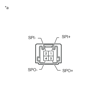
E422225C40
1.771,1.76 1.958,1.292 1.958,1.292 2.031,1.292 true 1.583,1.771 1.406,1.313 1.406,1.313 1.302,1.313 true 1.563,2.073 1.427,2.385 1.427,2.385 1.344,2.385 true 1.781,2.063 1.979,2.417 1.979,2.417 2.083,2.417 true 2.125,1.177 2.49,1.396 0.365,0.219 10 false SPI+ 0.969,1.208 1.344,1.375 0.375,0.167 10 false SPI- 2.146,2.344 2.635,2.51 0.49,0.167 10 false SPO+ 0.958,2.313 1.427,2.531 0.469,0.219 10 false SPO- 0.167,0.177 0.448,0.417 0.281,0.24 10 false *a
*a Component without harness connected
(Telephone Transceiver Assembly)


Remove the telephone transceiver assembly.

Click hereAudio / Visual / Telematics>TELEMATICS>TELEMATICS TRANSCEIVER>REMOVAL


b.

Measure the resistance according to the value(s) in the table below.

Standard Resistance:
Tester Connection Condition Specified Condition
3 (SPO+) - 1 (SPI+) Always Below 1 Ω
4 (SPO-) - 2 (SPI-) Always Below 1 Ω
1 (SPI+) - 2 (SPI-) Always 10 kΩ or higher
3 (SPO+) - 4 (SPO-) Always 10 kΩ or higher


Result:
Proceed to
OK
NG


OK

11.CHECK FRONT NO.3 SPEAKER ASSEMBLY

NG

REPLACE TELEPHONE TRANSCEIVER ASSEMBLY

11.CHECK FRONT NO.3 SPEAKER ASSEMBLY

Pre-procedure1

a.

Replace the front No. 3 speaker assembly with a new or known good one.

HINT:

Click hereAudio / Visual / Telematics>AUDIO / VIDEO>INSTRUMENT PANEL SPEAKER>REMOVAL


b.

Clear the DTCs.

HINT:

Click hereAudio / Visual / Telematics>AUDIO / VIDEO>AUDIO AND VISUAL SYSTEM (for Radio and Display Type, except 12.3 Inch Display)>DTC CHECK / CLEAR


Body Electrical > Navigation System > Clear DTCs
50002 212

Procedure1

c.

Recheck for DTCs and check that no DTCs are output.

HINT:

Click hereAudio / Visual / Telematics>AUDIO / VIDEO>AUDIO AND VISUAL SYSTEM (for Radio and Display Type, except 12.3 Inch Display)>DTC CHECK / CLEAR


Body Electrical > Navigation System > Trouble Codes
50001 212
OK:

No DTCs are output


Result:
Proceed to
OK
NG


Post-procedure1

d.

None


OK

END (FRONT NO. 3 SPEAKER ASSEMBLY IS DEFECTIVE)

NG