BRAKE CONTROL / DYNAMIC CONTROL SYSTEMS BRAKE ACTUATOR(for LHD) INSTALLATION
CAUTION / NOTICE / HINT
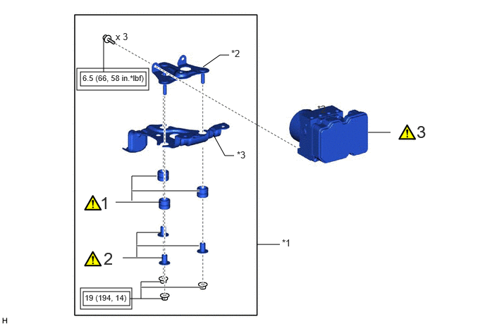
| Procedure | Part Name Code |

|

|

|
|
|---|---|---|---|---|---|
| 1 | BRAKE ACTUATOR BRACKET CUSHION | 44547B | ( ) |
- | - |
| 2 | NO. 1 BRAKE ACTUATOR CASE COLLAR | 44521A | () |
- | - |
| 3 | BRAKE ACTUATOR ASSEMBLY | 44510 | () |
- | - |
| *1 | BRAKE ACTUATOR BRACKET ASSEMBLY | *2 | NO. 1 BRAKE ACTUATOR BRACKET |
| *3 | NO. 2 BRAKE ACTUATOR BRACKET | - | - |

|
Tightening torque for "Major areas involving basic vehicle performance such as moving/turning/stopping": N*m (kgf*cm, ft.*lbf) | - | - |
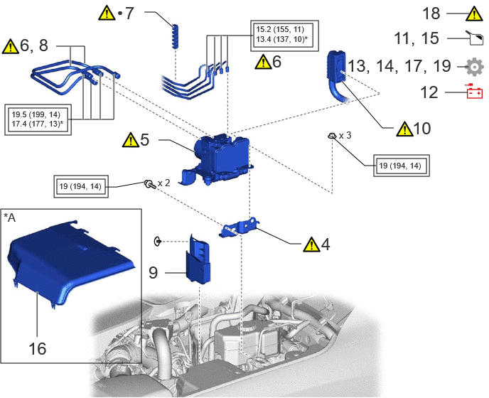
| Procedure | Part Name Code |
|
|
|
|
|---|---|---|---|---|---|
| 4 | NO. 3 BRAKE ACTUATOR BRACKET | 44593 | () |
- | - |
| 5 | BRAKE ACTUATOR WITH BRACKET | - | () |
- | - |
| 6 | CONNECT BRAKE TUBE | - | () |
- | - |
| 7 | NO. 2 BRAKE TUBE CLAMP | 47372 | () |
- | - |
| 8 | INSTALL BRAKE TUBE | - | () |
- | - |
| 9 | UPPER ENGINE SIDE UNDER COVER PLATE LH | 51478C | - | - | - |
| 10 | ENGINE ROOM MAIN WIRE | 82111 | () |
- | - |
| 11 | FILL RESERVOIR WITH BRAKE FLUID | - | - | - | - |
| 12 | CONNECT CABLE TO NEGATIVE BATTERY TERMINAL | - | - | - | - |
| 13 | ECU CONFIGURATION | - | - | - | () |
| 14 | UPDATE ECU SECURITY KEY | - | - | - | () |
| 15 | BLEED BRAKE SYSTEM | - | - | () |
- |
| 16 | ENGINE SIDE COVER LH | 51474B | - | - | - |
| 17 | PERFORM CALIBRATION | - | - | - | () |
| 18 | CHECK AND CLEAR DTC | - | - | - | - |
| 19 | INITIALIZATION AFTER RECONNECTING BATTERY TERMINAL | - | - | - | () |
| *A | except 1GR-FE | - | - |
|
|
Tightening torque for "Major areas involving basic vehicle performance such as moving/turning/stopping": N*m (kgf*cm, ft.*lbf) | * | For use with a union nut wrench |
| ● | Non-reusable part | - | - |
- NOTICE:
-
·
After replacing the brake actuator assembly, make sure to perform ECU configuration.
·After performing the ECU configuration procedure and update ECU security key procedure, make sure to perform the initialization procedure for when the cable has been disconnected and reconnected to the negative (-) battery terminal.
- HINT:
-
The parking brake indicator light (red) blinks when the ignition switch is turned to ON after replacing the brake actuator assembly. Operate the electric parking brake switch assembly to turn off the parking brake indicator light.
PROCEDURE

 44547B 1.INSTALL BRAKE ACTUATOR BRACKET CUSHION
|
|
|
44521A 2.INSTALL NO. 1 BRAKE ACTUATOR CASE COLLAR
|
|
|
- Torque:
- 19 N*m (194 kgf*cm, 14 ft.*lbf)
44510 3.INSTALL BRAKE ACTUATOR ASSEMBLY
|
|
|
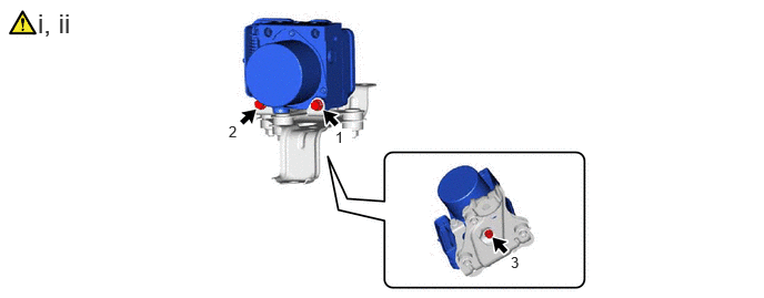
Temporarily install the brake actuator assembly to the brake actuator bracket assembly with the 3 bolts.
Tighten the 3 bolts in the order shown in the illustration.
- Torque:
- 6.5 N*m (66 kgf*cm, 58 in.*lbf)
44593 4.INSTALL NO. 3 BRAKE ACTUATOR BRACKET
|
|
|
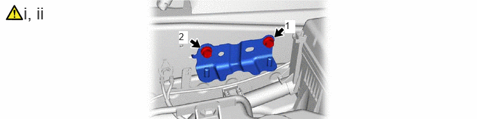
Temporarily install the No. 3 brake actuator bracket to the body with the 2 bolts.
Tighten the 2 bolts in the order shown in the illustration.
- Torque:
- 19 N*m (194 kgf*cm, 14 ft.*lbf)
5.INSTALL BRAKE ACTUATOR WITH BRACKET
|
|
|
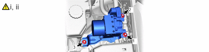
Temporarily install the brake actuator with bracket to the body with the 3 nuts.
Tighten the 3 nuts in the order shown in the illustration.
- Torque:
- 19 N*m (194 kgf*cm, 14 ft.*lbf)
6.CONNECT BRAKE TUBE
|
|
|
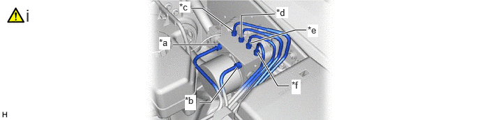
| *a | From 1st Chamber of Brake Booster with Master Cylinder Assembly | *b | From 2nd Chamber of Brake Booster with Master Cylinder Assembly |
| *c | To Front Disc Brake Cylinder Assembly RH | *d | To Front Disc Brake Cylinder Assembly LH |
| *e | To Rear Disc Brake Cylinder Assembly RH | *f | To Rear Disc Brake Cylinder Assembly LH |
Temporarily tighten the 6 brake tubes to the correct position on the brake actuator assembly as shown in the illustration.
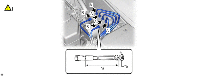
| *a | Torque Wrench Fulcrum Length | *b | Union Nut Wrench |
Using a union nut wrench, fully tighten the 4 brake tubes.
- Torque:
- Specified tightening torque (A) : 15.2 N*m (155 kgf*cm, 11 ft.*lbf)
- Specified tightening torque (B) : 19.5 N*m (199 kgf*cm, 14 ft.*lbf)
- HINT:
-
·
Calculate the torque wrench reading when changing the fulcrum length of the torque wrench.
Click hereGeneral>INTRODUCTION>REPAIR INSTRUCTION>PRECAUTION
·When using a union nut wrench (fulcrum length of 22 mm (0.866 in.)) + torque wrench (fulcrum length of 162 mm (6.38 in.)) (A):
13.4 N*m (137 kgf*cm, 10 ft.*lbf)
·When using a union nut wrench (fulcrum length of 20 mm (0.787 in.)) + torque wrench (fulcrum length of 162 mm (6.38 in.)) (B):
17.4 N*m (177 kgf*cm, 13 ft.*lbf)
47372 7.INSTALL NO. 2 BRAKE TUBE CLAMP
|
|
|
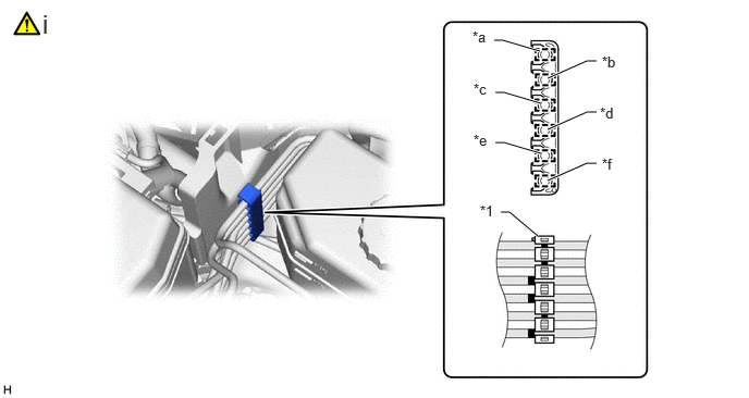
| *1 | No. 2 Brake Tube Clamp | - | - |
| *a | From 1st Chamber of Brake Booster with Master Cylinder Assembly | *b | From 2nd Chamber of Brake Booster with Master Cylinder Assembly |
| *c | To Rear Wheel Cylinder Assembly LH | *d | To Rear Wheel Cylinder Assembly RH |
| *e | To Front Wheel Cylinder Assembly LH | *f | To Front Wheel Cylinder Assembly RH |

|
Paint Mark | - | - |
Engage the 6 clamps and install a new No. 2 brake tube clamp to the brake tube as shown in the illustration.
8.INSTALL BRAKE TUBE
|
|
|
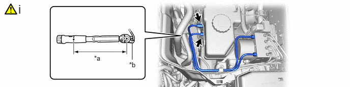
| *a | Torque Wrench Fulcrum Length | *b | Union Nut Wrench |
Temporarily tighten the 2 brake tubes.
Using a union nut wrench, fully tighten the 2 brake tubes.
- Torque:
- Specified tightening torque : 19.5 N*m (199 kgf*cm, 14 ft.*lbf)
- HINT:
-
·
Calculate the torque wrench reading when changing the fulcrum length of the torque wrench.
Click hereGeneral>INTRODUCTION>REPAIR INSTRUCTION>PRECAUTION
·When using a union nut wrench (fulcrum length of 20 mm (0.787 in.)) + torque wrench (fulcrum length of 162 mm (6.378 in.)):
17.4 N*m (177 kgf*cm, 13 ft.*lbf)
51478C 9.INSTALL UPPER ENGINE SIDE UNDER COVER PLATE LH
82111 10.CONNECT ENGINE ROOM MAIN WIRE
|
|
|
11.FILL RESERVOIR WITH BRAKE FLUID
12.CONNECT CABLE TO NEGATIVE BATTERY TERMINAL
for 1GR-FE:
for V35A-FTS:
for F33A-FTV:
13. ECU CONFIGURATION
14. UPDATE ECU SECURITY KEY
15.BLEED BRAKE SYSTEM
51474B 16.INSTALL ENGINE SIDE COVER LH (except 1GR-FE)
17.PERFORM CALIBRATION
18. CHECK AND CLEAR DTC
19. INITIALIZATION AFTER RECONNECTING BATTERY TERMINAL
Click hereGeneral>SETUP>WHEN DISCONNECTING OR RECONNECTING BATTERY TERMINAL>WORK PROCEDURE
- HINT:
-
When disconnecting and reconnecting the battery, there is an automatic learning function that completes learning when the respective system is used.
-
Click hereGeneral>SETUP>WHEN DISCONNECTING OR RECONNECTING BATTERY TERMINAL>AUTOMATIC LEARNING CHART