F33A-FTV LUBRICATION OIL PAN AND OIL LEVEL SENSOR INSTALLATION
CAUTION / NOTICE / HINT
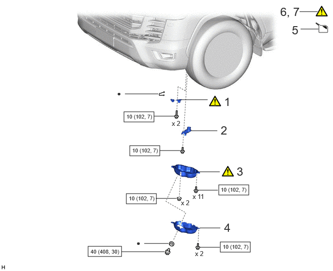
| Procedure | Part Name Code |

|

|

|
|
|---|---|---|---|---|---|
| 1 | ENGINE OIL LEVEL SENSOR | 89491 | ( ) |
- | - |
| 2 | OIL STRAINER SUB-ASSEMBLY | 15104 | - | - | |
| 3 | NO. 2 OIL PAN SUB-ASSEMBLY | 12102A | () |
- | - |
| 4 | OIL PAN COVER | 12140 | - | - | |
| 5 | ADD ENGINE OIL | - | - | () |
- |
| 6 | INSPECT ENGINE OIL LEVEL | - | () |
- | - |
| 7 | INSPECT FOR OIL LEAK | - | () |
- | - |

|
N*m (kgf*cm, ft.*lbf): Specified torque | ● | Non-reusable part |
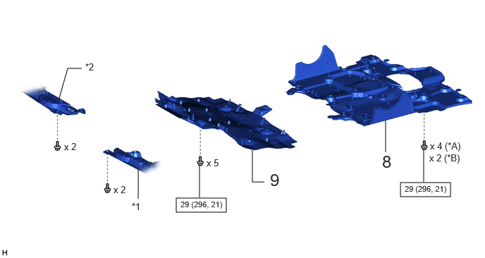
| Procedure | Part Name Code |
|
|
|
|
|---|---|---|---|---|---|
| 8 | NO. 2 ENGINE UNDER COVER ASSEMBLY | 51420 | - | - | - |
| 9 | NO. 1 ENGINE UNDER COVER ASSEMBLY | 51410 | - | - | - |
| *A | w/ Cover | *B | w/o Cover |
| *1 | ENGINE SIDE COVER SUB-ASSEMBLY LH | *2 | ENGINE SIDE COVER SUB-ASSEMBLY RH |
|
|
N*m (kgf*cm, ft.*lbf): Specified torque | - | - |
PROCEDURE

 89491 1.INSTALL ENGINE OIL LEVEL SENSOR
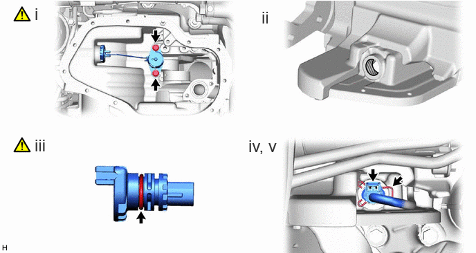
Install the engine oil level sensor with the 2 bolts.
- Torque:
- 10 N*m (102 kgf*cm, 7 ft.*lbf)
Remove any dirt or foreign matter from the engine oil level sensor connector installation hole.
Apply a light coat of engine oil to the O-ring of the engine oil level sensor.
Install a new clip to the engine oil level sensor.
Connect the engine oil level sensor connector.
15104 2.INSTALL OIL STRAINER SUB-ASSEMBLY
12102A 3.INSTALL NO. 2 OIL PAN SUB-ASSEMBLY
|
|
Click here() |
12140 4.INSTALL OIL PAN COVER
5.ADD ENGINE OIL
6.INSPECT ENGINE OIL LEVEL
7.INSPECT FOR OIL LEAK
51420 8.INSTALL NO. 2 ENGINE UNDER COVER ASSEMBLY
51410 9.INSTALL NO. 1 ENGINE UNDER COVER ASSEMBLY
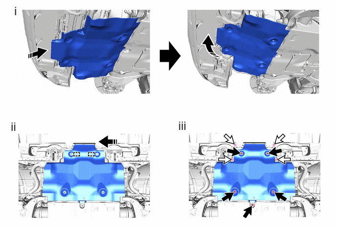

|
Bolt A |

|
Bolt B |

|
Install in this Direction | - | - |
After attaching the 2 temporary holding guides of the No. 1 engine under cover assembly to the vehicle frame, set the No. 1 engine under cover assembly to the vehicle side while pulling the engine side cover sub-assembly RH and engine side cover sub-assembly LH as shown in the illustration.
Move the side of the No. 1 engine under cover assembly facing the front of the vehicle and attach the 2 temporary holding guides to the vehicle frame.
Install the 5 bolts (A) and 4 bolts (B).
- Torque:
- for bolt (A) : 29 N*m (296 kgf*cm, 21 ft.*lbf)