F33A-FTV ENGINE MECHANICAL ENGINE UNIT REASSEMBLY
CAUTION / NOTICE / HINT
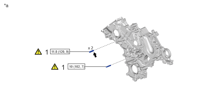
| Procedure | Part Name Code |

|

|

|
|
|---|---|---|---|---|---|
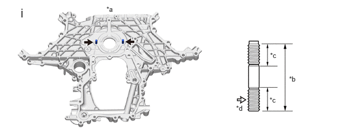
| 1 | STUD BOLT | - | ( ) |
- | - |
| *a | Timing Chain OR Belt Cover Sub-assembly Side | - | - |

|
N*m (kgf*cm, ft.*lbf): Specified torque |

|
Toyota Genuine Adhesive 1324, Three Bond 1324 or equivalent |
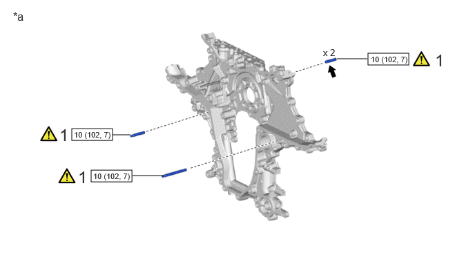
| Procedure | Part Name Code |
|
|
|
|
|---|---|---|---|---|---|
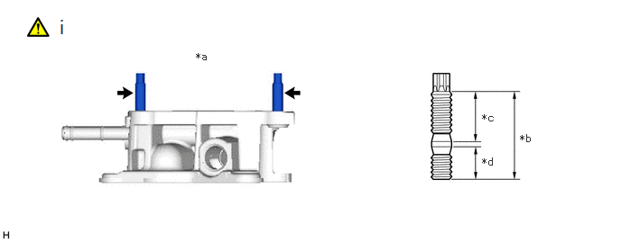
| 1 | STUD BOLT | - | () |
- | - |
| *a | Timing Chain Cover Assembly Side | - | - |
|
|
N*m (kgf*cm, ft.*lbf): Specified torque |
|
Toyota Genuine Adhesive 1324, Three Bond 1324 or equivalent |
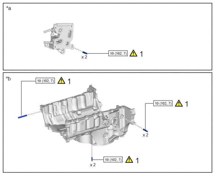
| Procedure | Part Name Code |
|
|
|
|
|---|---|---|---|---|---|
| 1 | STUD BOLT | - | () |
- | - |
| *a | No. 1 Oil Cooler Bracket Side | *b | Oil Pan Sub-assembly Side |
|
|
N*m (kgf*cm, ft.*lbf): Specified torque | - | - |
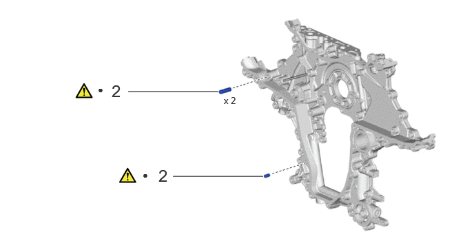
| Procedure | Part Name Code |
|
|
|
|
|---|---|---|---|---|---|
| 2 | STRAIGHT PIN | - | () |
- | - |
| ● | Non-reusable part | - | - |
| Procedure | Part Name Code |
|
|
|
|
|---|---|---|---|---|---|
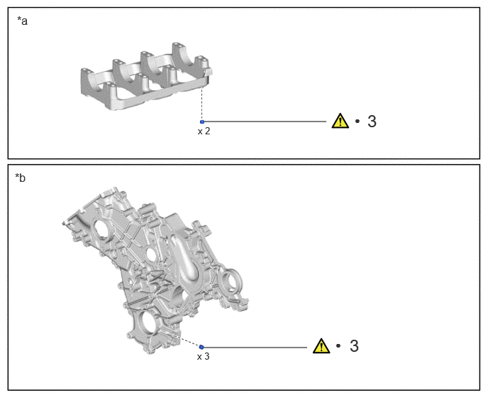
| 3 | RING PIN | - | () |
- | - |
| *a | Crankshaft Bearing Cap Sub-assembly Side | *b | Timing Chain OR Belt Cover Sub-assembly Side |
| ● | Non-reusable part | - | - |
| Procedure | Part Name Code |
|
|
|
|
|---|---|---|---|---|---|
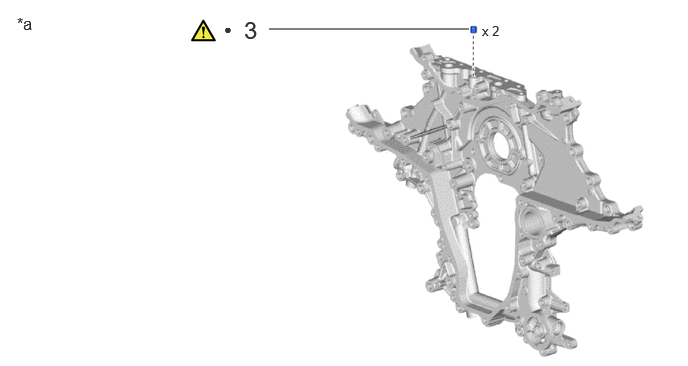
| 3 | RING PIN | - | () |
- | - |
| *a | Timing Chain Cover Assembly Side | - | - |
| ● | Non-reusable part | - | - |
| Procedure | Part Name Code |
|
|
|
|
|---|---|---|---|---|---|
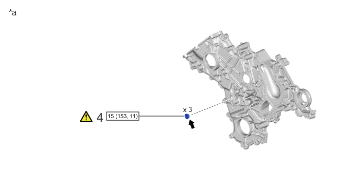
| 4 | STRAIGHT SCREW PLUG | - | () |
- | - |
| *a | Timing Chain OR Belt Cover Sub-assembly Side | - | - |
|
|
N*m (kgf*cm, ft.*lbf): Specified torque |
|
Toyota Genuine Adhesive 1324, Three Bond 1324 or equivalent |
| Procedure | Part Name Code |
|
|
|
|
|---|---|---|---|---|---|
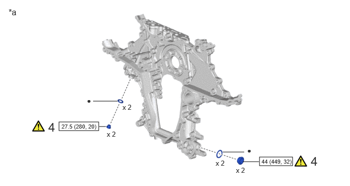
| 4 | STRAIGHT SCREW PLUG | - | () |
- | - |
| *a | Timing Chain Cover Assembly Side | - | - |
|
|
N*m (kgf*cm, ft.*lbf): Specified torque | ● | Non-reusable part |
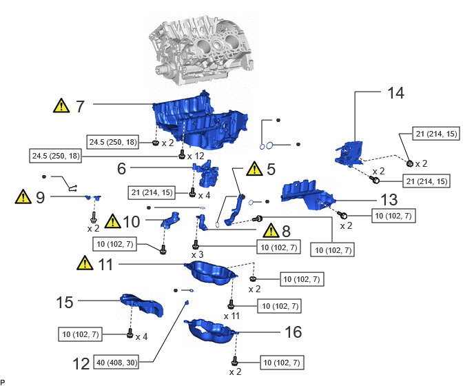
| Procedure | Part Name Code |
|
|
|
|
|---|---|---|---|---|---|
| 5 | NO. 1 OIL PIPE | 15771K | () |
- | - |
| 6 | OIL PUMP ASSEMBLY | 15100 | - | - | - |
| 7 | OIL PAN SUB-ASSEMBLY | 12101 | () |
- | - |
| 8 | OIL PUMP OUTLET PIPE | 15413 | () |
- | - |
| 9 | ENGINE OIL LEVEL SENSOR | 89491 | () |
- | - |
| 10 | OIL STRAINER SUB-ASSEMBLY | 15104 | () |
- | - |
| 11 | NO. 2 OIL PAN SUB-ASSEMBLY | 12102A | () |
- | - |
| 12 | OIL PAN DRAIN PLUG | 12101A | - | - | - |
| 13 | NO. 2 OIL PAN COVER SILENCER | 12145 | - | - | - |
| 14 | NO. 1 OIL COOLER BRACKET | 15781 | - | - | - |
| 15 | OIL PAN COVER | 12143 | - | - | - |
| 16 | OIL PAN COVER | 12140 | - | - | - |
|
|
N*m (kgf*cm, ft.*lbf): Specified torque | ● | Non-reusable part |
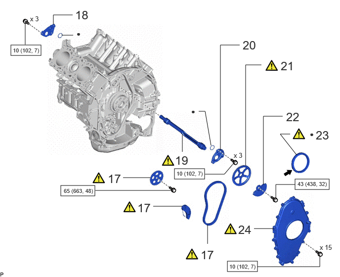
| Procedure | Part Name Code |
|
|
|
|
|---|---|---|---|---|---|
| 17 | OIL PUMP CHAIN AND OIL PUMP DRIVE SHAFT SPROCKET | - | () |
- | - |
| 18 | OIL HOLE COVER PLATE | 11494 | - | - | - |
| 19 | NO. 1 BALANCESHAFT SUB-ASSEMBLY | 13601A | () |
- | - |
| 20 | BALANCESHAFT THRUST SPACER | 13635 | - | - | - |
| 21 | NO. 1 BALANCESHAFT DRIVEN GEAR | 13632 | () |
- | - |
| 22 | REAR BALANCESHAFT WEIGHT | 13624 | - | - | - |
| 23 | REAR ENGINE OIL SEAL | 11381A | () |
- | - |
| 24 | REAR ENGINE OIL SEAL RETAINER | 11381 | () |
- | - |
|
|
N*m (kgf*cm, ft.*lbf): Specified torque | ● | Non-reusable part |
|
|
MP grease | - | - |
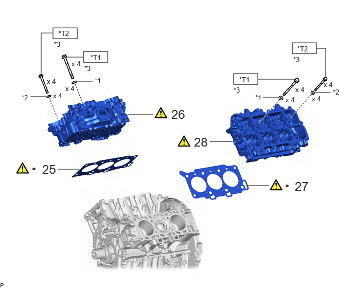
| Procedure | Part Name Code |
|
|
|
|
|---|---|---|---|---|---|
| 25 | CYLINDER HEAD GASKET | 11115 | () |
- | - |
| 26 | CYLINDER HEAD SUB-ASSEMBLY | 11101 | () |
- | - |
| 27 | NO. 2 CYLINDER HEAD GASKET | 11116 | () |
- | - |
| 28 | CYLINDER HEAD LH | 11102 | () |
- | - |
| *1 | CYLINDER HEAD SET PLATE WASHER | *2 | CYLINDER HEAD SET BOLT SPACER |
| *3 | CYLINDER HEAD SET BOLT | - | - |
|
|
N*m (kgf*cm, ft.*lbf): Specified torque | ● | Non-reusable part |
| *T1 | 1st: 100 (1020, 74) 2nd: Turn 90° 3rd: Turn 90° 4th: Turn 90° |
*T2 | 1st: 50 (510, 37) 2nd: Turn 90° 3rd: Turn 90° 4th: Turn 90° |
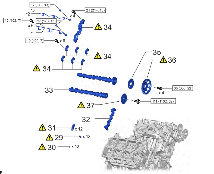
| Procedure | Part Name Code |
|
|
|
|
|---|---|---|---|---|---|
| 29 | VALVE LASH ADJUSTER ASSEMBLY | 13750 | () |
- | - |
| 30 | VALVE STEM CAP | 13716 | () |
- | - |
| 31 | NO. 1 VALVE ROCKER ARM SUB-ASSEMBLY | 13801 | () |
- | - |
| 32 | NO. 2 CAMSHAFT BEARING CAP | - | - | - | - |
| 33 | INTAKE CAMSHAFT SUB-ASSEMBLY RH AND EXHAUST CAMSHAFT SUB-ASSEMBLY RH | - | - | - | - |
| 34 | NO. 1 CAMSHAFT BEARING CAP AND NO. 3 CAMSHAFT BEARING CAP | - | () |
- | - |
| 35 | CAMSHAFT TIMING SPROCKET | 13523G | - | - | - |
| 36 | PUMP DRIVE SHAFT GEAR | 13522 | () |
- | - |
| 37 | NO. 2 CAMSHAFT TIMING SPROCKET | 13529G | () |
- | - |
| *1 | NO. 1 CAMSHAFT OIL FEED PIPE SUB-ASSEMBLY | *2 | NO. 2 CAMSHAFT OIL FEED PIPE SUB-ASSEMBLY |
| *3 | UNION BOLT | - | - |
|
|
N*m (kgf*cm, ft.*lbf): Specified torque | - | - |
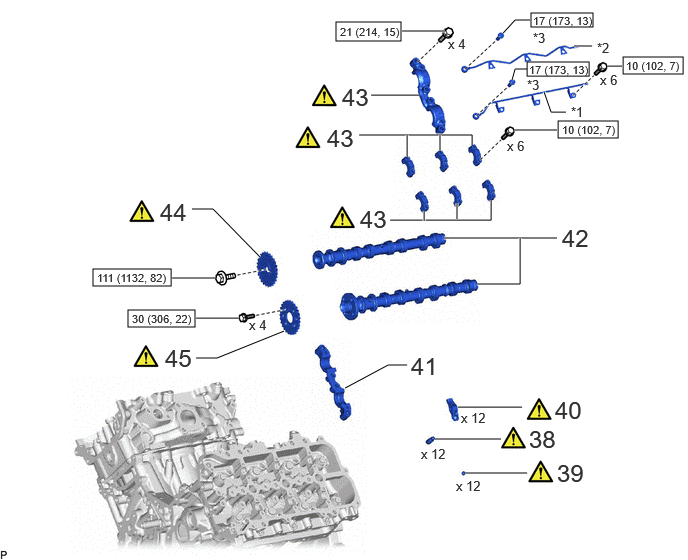
| Procedure | Part Name Code |
|
|
|
|
|---|---|---|---|---|---|
| 38 | VALVE LASH ADJUSTER ASSEMBLY | 13750 | () |
- | - |
| 39 | VALVE STEM CAP | 13716 | () |
- | - |
| 40 | NO. 1 VALVE ROCKER ARM SUB-ASSEMBLY | 13801 | () |
- | - |
| 41 | NO. 5 CAMSHAFT BEARING CAP | - | - | - | - |
| 42 | INTAKE CAMSHAFT SUB-ASSEMBLY LH AND EXHAUST CAMSHAFT SUB-ASSEMBLY LH | - | - | - | - |
| 43 | NO. 3 CAMSHAFT BEARING CAP AND NO. 4 CAMSHAFT BEARING CAP | - | () |
- | - |
| 44 | NO. 2 CAMSHAFT TIMING SPROCKET ASSEMBLY | 13529G | () |
- | - |
| 45 | CAMSHAFT TIMING SPROCKET | 13523G | () |
- | - |
| *1 | NO. 3 CAMSHAFT OIL FEED PIPE SUB-ASSEMBLY | *2 | NO. 4 CAMSHAFT OIL FEED PIPE SUB-ASSEMBLY |
| *3 | UNION BOLT | - | - |
|
|
N*m (kgf*cm, ft.*lbf): Specified torque | - | - |
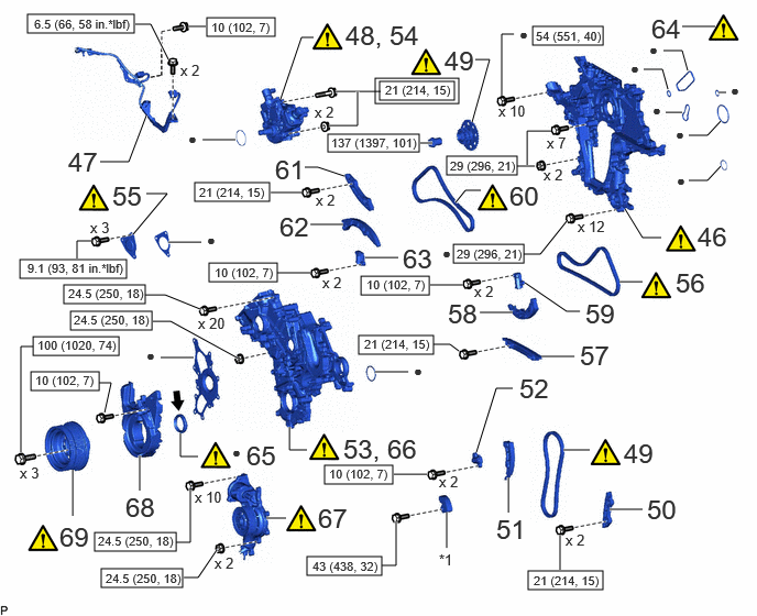
| Procedure | Part Name Code |
|
|
|
|
|---|---|---|---|---|---|
| 46 | TIMING CHAIN COVER ASSEMBLY | 11310 | () |
- | - |
| 47 | FUEL PUMP MOTOR WIRE | 23243C | - | - | - |
| 48 | TEMPORARILY INJECTION OR SUPPLY PUMP ASSEMBLY | 22100 | () |
- | - |
| 49 | NO. 1 CHAIN SUB-ASSEMBLY AND SUPPLY PUMP SHAFT SPROCKET | 13506A | () |
- | - |
| 50 | NO. 1 CHAIN VIBRATION DAMPER | 13561 | - | - | - |
| 51 | CHAIN TENSIONER SLIPPER | 13559 | - | - | - |
| 52 | NO. 1 CHAIN TENSIONER ASSEMBLY | 13540 | - | - | - |
| 53 | TEMPORARILY TIMING CHAIN OR BELT COVER SUB-ASSEMBLY | 11302 | () |
- | - |
| 54 | INSTALL INJECTION OR SUPPLY PUMP ASSEMBLY | 22100 | () |
- | - |
| 55 | TIMING CHAIN COVER PLATE | 11324 | () |
- | - |
| 56 | NO.2 CHAIN SUB-ASSEMBLY | 13507 | () |
- | - |
| 57 | NO. 3 CHAIN VIBRATION DAMPER | 13563 | - | - | - |
| 58 | CHAIN TENSIONER SLIPPER LH | 13559F | - | - | - |
| 59 | NO. 3 CHAIN TENSIONER ASSEMBLY | 13560A | - | - | - |
| 60 | NO. 2 CHAIN SUB-ASSEMBLY | 13507 | () |
- | - |
| 61 | NO. 2 CHAIN VIBRATION DAMPER | 13562 | - | - | - |
| 62 | CHAIN TENSIONER SLIPPER RH | 13559E | - | - | - |
| 63 | NO. 2 CHAIN TENSIONER ASSEMBLY | 13550 | - | - | - |
| 64 | SET NO. 1 CYLINDER TO TDC/COMPRESSION | - | () |
- | - |
| 65 | TIMING CHAIN OR BELT COVER OIL SEAL | 11302A | () |
- | - |
| 66 | TIMING CHAIN OR BELT COVER SUB-ASSEMBLY | 11302 | () |
- | - |
| 67 | ENGINE WATER PUMP ASSEMBLY | 16100 | () |
- | - |
| 68 | NO. 2 TIMING CHAIN COVER INSULATOR | 11339D | - | - | - |
| 69 | CRANKSHAFT PULLEY SUB-ASSEMBLY | 13408 | () |
- | - |
| *1 | NO. 2 BALANCESHAFT | - | - |

|
Tightening torque for "Major areas involving basic vehicle performance such as moving/turning/stopping": N*m (kgf*cm, ft.*lbf) |
|
N*m (kgf*cm, ft.*lbf): Specified torque |
| ● | Non-reusable part |
|
MP grease |
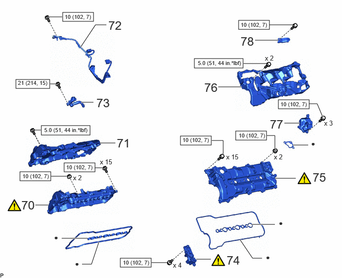
| Procedure | Part Name Code |
|
|
|
|
|---|---|---|---|---|---|
| 70 | CYLINDER HEAD COVER RH | 11211 | () |
- | - |
| 71 | CYLINDER HEAD COVER SILENCER | 11224 | - | - | - |
| 72 | FUEL PUMP MOTOR WIRE | 23243C | - | - | - |
| 73 | NO. 4 NOZZLE LEAKAGE PIPE | 23764A | - | - | - |
| 74 | OIL SEPARATOR ASSEMBLY | 12270K | () |
- | - |
| 75 | CYLINDER HEAD COVER LH | 11212B | () |
- | - |
| 76 | CYLINDER HEAD COVER LH SILENCER | 11225 | - | - | - |
| 77 | OIL SEPARATOR HOLDER | 12277 | - | - | - |
| 78 | FUEL PIPE BRACKET | 23211M | - | - | - |
|
|
N*m (kgf*cm, ft.*lbf): Specified torque | ● | Non-reusable part |
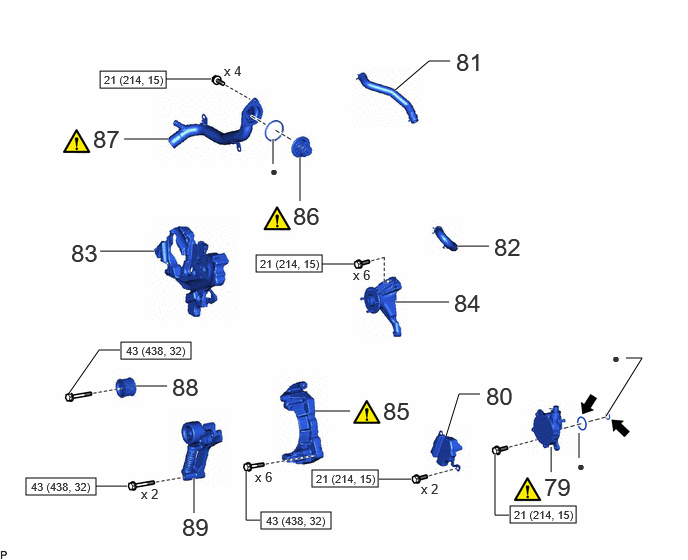
| Procedure | Part Name Code |
|
|
|
|
|---|---|---|---|---|---|
| 79 | VACUUM PUMP ASSEMBLY | 29300 | () |
- | - |
| 80 | PLATE INSULATOR | 21989B | - | - | - |
| 81 | NO. 10 WATER BY-PASS HOSE | 16293 | - | - | - |
| 82 | WATER HOSE | 16571E | - | - | - |
| 83 | TIMING CHAIN COVER INSULATOR | 11336B | - | - | - |
| 84 | FAN BRACKET SUB-ASSEMBLY | 16307A | - | - | - |
| 85 | GENERATOR BRACKET | 12511C | () |
- | - |
| 86 | THERMOSTAT | 16331A | () |
- | - |
| 87 | WATER INLET | 16321 | () |
- | - |
| 88 | IDLER PULLEY SUB-ASSEMBLY | 16603B | - | - | - |
| 89 | V-RIBBED BELT TENSIONER ASSEMBLY | 16620D | - | - | - |
|
|
N*m (kgf*cm, ft.*lbf): Specified torque | ● | Non-reusable part |
|
|
Engine oil | - | - |
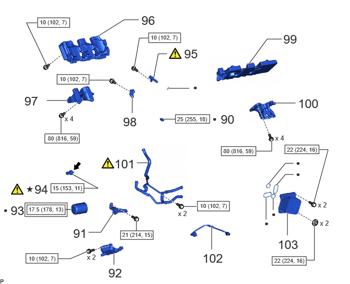
| Procedure | Part Name Code |
|
|
|
|
|---|---|---|---|---|---|
| 90 | CYLINDER BLOCK WATER DRAIN COCK PLUG | 11415A | - | - | - |
| 91 | NO. 1 COMPRESSOR MOUNTING BRACKET | 88431 | - | - | - |
| 92 | OIL FILTER RECEIVER | 15674 | - | - | - |
| 93 | OIL FILTER SUB-ASSEMBLY | 15601 | - | - | - |
| 94 | OIL PRESSURE SENDER GAGE ASSEMBLY | 83520 | () |
- | - |
| 95 | CRANKSHAFT POSITION SENSOR | 11401G | () |
- | - |
| 96 | NO. 1 CYLINDER BLOCK INSULATOR | 12581A | - | - | - |
| 97 | ENGINE MOUNTING BRACKET RH | 12315A | - | - | - |
| 98 | NO. 2 WIRING HARNESS CLAMP BRACKET | - | - | - | - |
| 99 | NO. 2 CYLINDER BLOCK INSULATOR | 12582A | - | - | - |
| 100 | ENGINE MOUNTING BRACKET LH | 12325A | - | - | - |
| 101 | NO. 2 WATER BY-PASS PIPE SUB-ASSEMBLY | 16207 | () |
- | - |
| 102 | NO. 1 CONNECTING WIRE | 27148D | - | - | - |
| 103 | OIL COOLER ASSEMBLY | 15710 | - | - | - |
|
|
Tightening torque for "Major areas involving basic vehicle performance such as moving/turning/stopping": N*m (kgf*cm, ft.*lbf) |
|
N*m (kgf*cm, ft.*lbf): Specified torque |
| ● | Non-reusable part |
|
Toyota Genuine Adhesive 1344, Three Bond 1344 or equivalent |
| ★ | Precoated part | - | - |
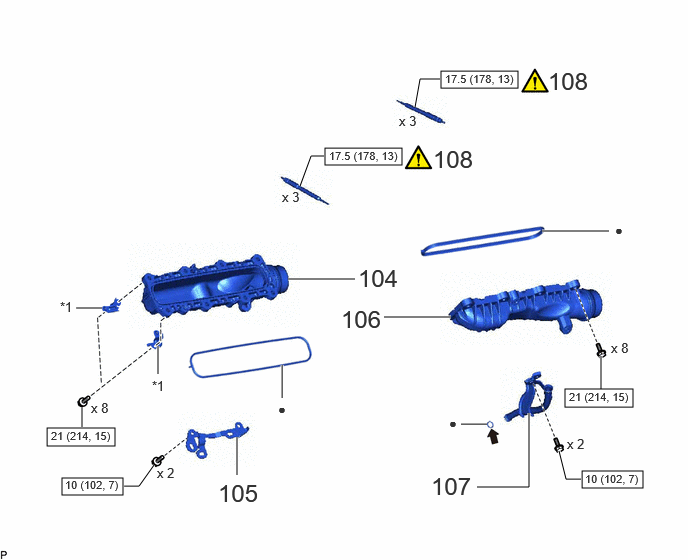
| Procedure | Part Name Code |
|
|
|
|
|---|---|---|---|---|---|
| 104 | INTAKE MANIFOLD | 17111 | - | - | - |
| 105 | NO. 2 WIRE HARNESS CLAMP | - | - | - | - |
| 106 | NO. 2 INTAKE MANIFOLD | 17112 | - | - | - |
| 107 | ENGINE OIL LEVEL DIPSTICK GUIDE | 11452 | - | - | - |
| 108 | GLOW PLUG ASSEMBLY | 19850 | () |
- | - |
| *1 | MANIFOLD STAY | - | - |
|
|
N*m (kgf*cm, ft.*lbf): Specified torque | ● | Non-reusable part |
|
|
Engine oil | - | - |
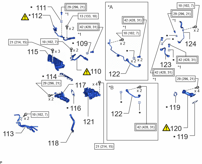
| Procedure | Part Name Code |
|
|
|
|
|---|---|---|---|---|---|
| 109 | GASKET | 23811K | - | - | - |
| 110 | NO. 1 FUEL PIPE | 23811G | () |
- | - |
| 111 | GASKET | 23801N | - | - | - |
| 112 | NO. 5 NOZZLE LEAKAGE PIPE | 23765 | () |
- | - |
| 113 | NO. 2 FUEL PIPE | 23812D | - | - | - |
| 114 | TURBO OIL INLET GASKET | 15471 | - | - | - |
| 115 | TURBOCHARGER STAY | 17293 | - | - | - |
| 116 | WATER OUTLET HOUSING GASKET | 16343 | - | - | - |
| 117 | WATER OUTLET | 16331 | - | - | - |
| 118 | NO. 4 OIL COOLER HOSE | 15776A | - | - | - |
| 119 | WATER OUTLET GASKET | 16341 | - | - | - |
| 120 | NO. 2 WATER OUTLET PIPE | 16335B | () |
- | - |
| 121 | DIESEL FUEL FILTER ASSEMBLY | 23300D | - | - | - |
| 122 | NO. 3 FUEL PIPE | 23815D | - | - | - |
| 123 | NO. 4 FUEL PIPE | 23816 | - | - | - |
| 124 | NO. 3 NOZZLE LEAKAGE PIPE | 23763 | - | - | - |
| *A | w/ DPF | *B | w/o DPF |
| *1 | UNION BOLT | - | - |
|
|
Tightening torque for "Major areas involving basic vehicle performance such as moving/turning/stopping": N*m (kgf*cm, ft.*lbf) |
|
N*m (kgf*cm, ft.*lbf): Specified torque |
| ● | Non-reusable part | - | - |
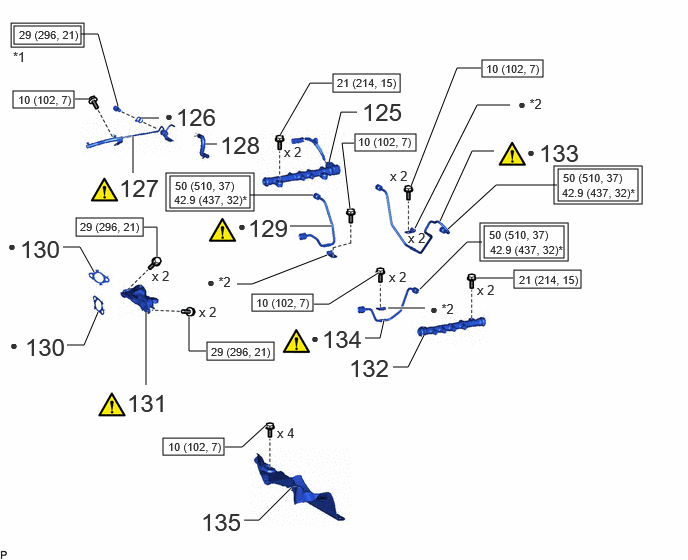
| Procedure | Part Name Code |
|
|
|
|
|---|---|---|---|---|---|
| 125 | COMMON RAIL ASSEMBLY (for Bank 1) | 23810A | - | - | - |
| 126 | FUEL PIPE GASKET | 23804H | - | - | - |
| 127 | NO. 5 FUEL PIPE SUB-ASSEMBLY | 23805B | () |
- | - |
| 128 | FUEL HOSE | 23802F | - | - | - |
| 129 | NO. 4 INJECTION PIPE SUB-ASSEMBLY | 23704 | () |
- | - |
| 130 | WATER OUTLET GASKET | 16341 | - | - | - |
| 131 | NO. 1 WATER OUTLET PIPE | 16332 | () |
- | - |
| 132 | COMMON RAIL ASSEMBLY (for Bank 2) | 23820A | - | - | - |
| 133 | NO. 6 INJECTION PIPE SUB-ASSEMBLY | 23706 | () |
- | - |
| 134 | NO. 5 INJECTION PIPE SUB-ASSEMBLY | 23705 | () |
- | - |
| 135 | INJECTION PUMP INSULATOR | 22815A | - | - | - |
| *1 | UNION BOLT | *2 | NO. 1 INJECTION PIPE CLAMP |
|
|
Tightening torque for "Major areas involving basic vehicle performance such as moving/turning/stopping": N*m (kgf*cm, ft.*lbf) |
|
N*m (kgf*cm, ft.*lbf): Specified torque |
| * | For use with union nut wrench | ● | Non-reusable part |
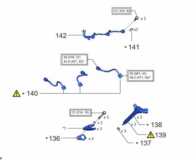
| Procedure | Part Name Code |
|
|
|
|
|---|---|---|---|---|---|
| 136 | NOZZLE HOLDER GASKET | 23682 | - | - | - |
| 137 | INJECTION NOZZLE SEAT | 11176 | - | - | - |
| 138 | O-RING | - | - | - | - |
| 139 | INJECTOR ASSEMBLY | 23670 | () |
- | - |
| 140 | INJECTION PIPE SUB-ASSEMBLY | - | () |
- | - |
| 141 | GASKET | 23760A | - | - | - |
| 142 | NO. 2 NOZZLE LEAKAGE PIPE | 23762B | - | - | - |
| *1 | NO. 1 NOZZLE HOLDER CLAMP | - | - |
|
|
Tightening torque for "Major areas involving basic vehicle performance such as moving/turning/stopping": N*m (kgf*cm, ft.*lbf) |
|
N*m (kgf*cm, ft.*lbf): Specified torque |
| * | For use with SST or union nut wrench | ● | Non-reusable part |
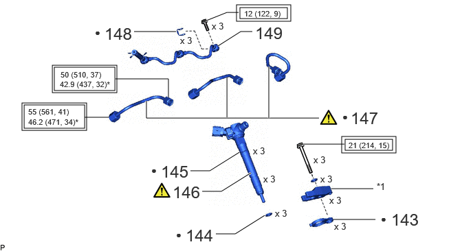
| Procedure | Part Name Code |
|
|
|
|
|---|---|---|---|---|---|
| 143 | NOZZLE HOLDER GASKET | 23682 | - | - | - |
| 144 | INJECTION NOZZLE SEAT | 11176 | - | - | - |
| 145 | O-RING | - | - | - | - |
| 146 | INJECTOR ASSEMBLY | 23670 | () |
- | - |
| 147 | INJECTION PIPE SUB-ASSEMBLY | - | () |
- | - |
| 148 | GASKET | 23760A | - | - | - |
| 149 | NO. 1 NOZZLE LEAKAGE PIPE | 23761A | - | - | - |
| *1 | NO. 1 NOZZLE HOLDER CLAMP | - | - |
|
|
Tightening torque for "Major areas involving basic vehicle performance such as moving/turning/stopping": N*m (kgf*cm, ft.*lbf) | * | For use with SST or union nut wrench |
| ● | Non-reusable part | - | - |
CAUTION / NOTICE / HINT
- NOTICE:
-
This procedure includes the installation of small-head bolts. Refer to Small-Head Bolts of Basic Repair Hint to identify the small-head bolts.
-
Click hereGeneral>INTRODUCTION>REPAIR INSTRUCTION>PRECAUTION
PROCEDURE

 1.INSTALL STUD BOLT
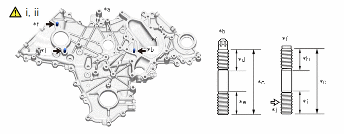
| *a | Timing Chain OR Belt Cover Sub-assembly Side | *b | Stud Bolt A |
| *c | 44 mm (1.73 in.) | *d | 19 mm (0.748 in.) |
| *e | 16 mm (0.630 in.) | *f | Stud Bolt B |
| *g | 44 mm (1.73 in.) | *h | 17 mm (0.669 in.) |
| *i | 15 mm (0.591 in.) | *j | Adhesive |
Using an E8 "TORX" socket wrench, install the stud bolt A.
- Torque:
- 10 N*m (102 kgf*cm, 7 ft.*lbf)
Apply adhesive to the sud bolt B, install the stud bolt B.
- Adhesive:
-
Toyota Genuine Adhesive 1324, Three Bond 1324 or equivalent
- Torque:
- 11.8 N*m (120 kgf*cm, 9 ft.*lbf)
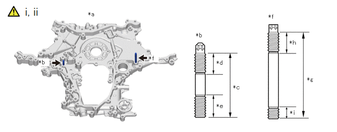
| *a | Timing Chain Cover Assembly Front Side | *b | Stud Bolt A |
| *c | 44 mm (1.73 in.) | *d | 19 mm (0.748 in.) |
| *e | 16 mm (0.630 in.) | *f | Stud Bolt B |
| *g | 83 mm (3.27 in.) | *h | 20 mm (0.787 in.) |
| *i | 13 mm (0.512 in.) | - | - |
Using an E8 "TORX" socket wrench, install the stud bolt A.
- Torque:
- 10 N*m (102 kgf*cm, 7 ft.*lbf)
Using an E8 "TORX" socket wrench, remove the stud bolt B.
- Torque:
- 10 N*m (102 kgf*cm, 7 ft.*lbf)
| *a | Timing Chain Cover Assembly Rear Side | *b | 40 mm (1.57 in.) |
| *c | 12 mm (0.472 in.) | *d | Adhesive |
Apply adhesive to the sud bolt , install the stud bolt.
- Adhesive:
-
Toyota Genuine Adhesive 1324, Three Bond 1324 or equivalent
- Torque:
- 10 N*m (102 kgf*cm, 7 ft.*lbf)
| *a | No. 1 Oil Cooler Bracket Side | *b | 35 mm (1.38 in.) |
| *c | 20 mm (0.787 in.) | *d | 13 mm (0.512 in.) |
Using an E8 "TORX" socket wrench, install the stud bolt.
- Torque:
- 10 N*m (102 kgf*cm, 7 ft.*lbf)
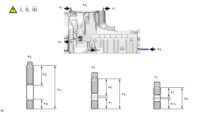
| *a | Oil Pan Sub-assembly Side | *b | Stud Bolt A |
| *c | 55 mm (2.17 in.) | *d | 25 mm (0.984 in.) |
| *e | 12 mm (0.472 in.) | *f | Stud Bolt B |
| *g | 35 mm (1.38 in.) | *h | 20 mm (0.787 in.) |
| *i | 13 mm (0.512 in.) | *j | Stud Bolt C |
| *k | 19 mm (0.748 in.) | *l | 9 mm (0.354 in.) |
| *m | 9 mm (0.354 in.) | - | - |
Using an E7 "TORX" socket wrench, install the stud bolt A.
- Torque:
- 10 N*m (102 kgf*cm, 7 ft.*lbf)
Using an E8 "TORX" socket wrench, install the stud bolt B.
- Torque:
- 10 N*m (102 kgf*cm, 7 ft.*lbf)
Using an E6 "TORX" socket wrench, install the stud bolt C.
- Torque:
- 10 N*m (102 kgf*cm, 7 ft.*lbf)
2.INSTALL STRAIGHT PIN
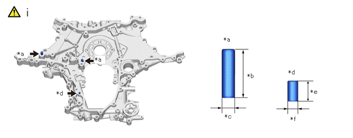
| *a | Straight Pin A | *b | 36 mm (1.42 in.) |
| *c | 10 mm (0.394 in.) | *d | Straight Pin B |
| *e | 15 mm (0.591 in.) | *f | 8 mm (0.315 in.) |
Using a plastic-faced hammer, tap in new straight pins.
- Standard protrusion height:
-
Straight Pin Protrusion Height A 18 to 20 mm (0.709 to 0.787 in.) B 5.5 to 7.5 mm (0.217 to 0.295 in.)
3.INSTALL RING PIN
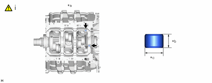
| *a | Crankshaft Bearing Cap Sub-assembly Side | *b | 8 mm (0.315 in.) |
| *c | 11 mm (0.433 in.) | - | - |
Using a plastic-faced hammer, tap in new ring pins.
- Standard protrusion height:
-
3.0 to 5.0 mm (0.118 to 0.197 in.)
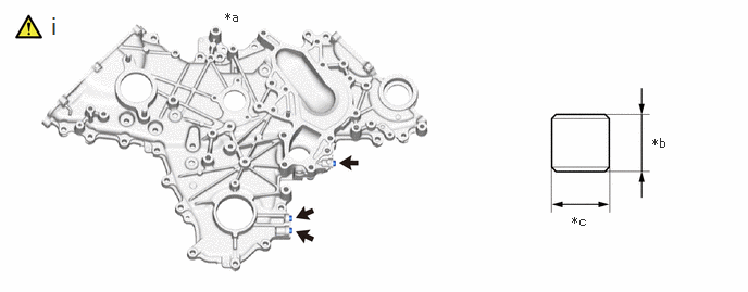
| *a | Timing Chain OR Belt Cover Sub-assembly Side | *b | 10 mm (0.394 in.) |
| *c | 11 mm (0.433 in.) | - | - |
Using a plastic-faced hammer, tap in new ring pins.
- Standard protrusion height:
-
4.7 to 5.7 mm (0.185 to 0.224 in.)
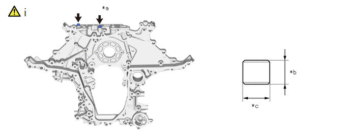
| *a | Timing Chain Cover Assembly Side | *b | 10 mm (0.394 in.) |
| *c | 11 mm (0.433 in.) | - | - |
Using a plastic-faced hammer, tap in new ring pins.
- Standard protrusion height:
-
6.25 to 6.75 mm (0.246 to 0.266 in.)
4.INSTALL STRAIGHT SCREW PLUG
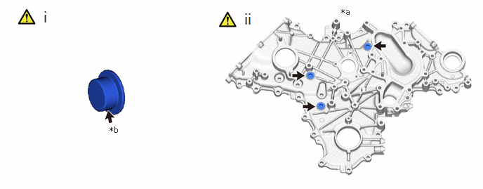
| *a | Timing Chain OR Belt Cover Sub-assembly Side | *b | Adhesive |
Apply adhesive to the straight screw plug.
- Adhesive:
-
Toyota Genuine Adhesive 1324, Three Bond 1324 or equivalent
Using a 10 mm hexagon wrench, install the straight screw plugs.
- Torque:
- 15 N*m (153 kgf*cm, 11 ft.*lbf)
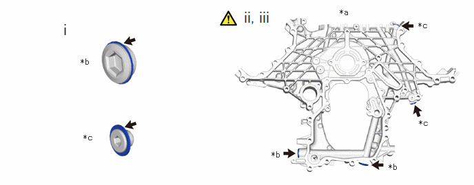
| *a | Timing Chain Cover Assembly Side | *b | Straight Screw Plug A |
| *c | Straight Screw Plug B | - | - |
Install new gasket to the straight screw plug.
Using a 14 mm hexagon wrench, install the straight screw plug A.
- Torque:
- 44 N*m (449 kgf*cm, 32 ft.*lbf)
Using a 6 mm hexagon wrench, install the straight screw plug B.
- Torque:
- 27.5 N*m (280 kgf*cm, 20 ft.*lbf)
15771K 5.INSTALL NO. 1 OIL PIPE
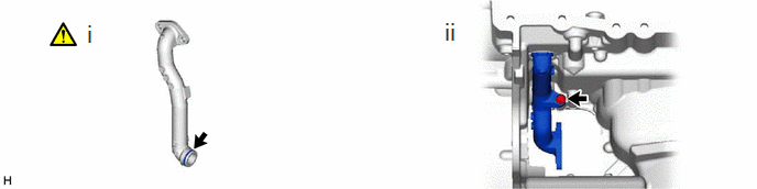
Install a new O-ring and apply engine oil.
Install the No. 1 oil pipe with the bolt.
- Torque:
- 10 N*m (102 kgf*cm, 7 ft.*lbf)
15100 6.INSTALL OIL PUMP ASSEMBLY
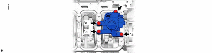
| *a | Bolt A | *b | Bolt B |
Install the oil pump assembly with the 4 bolts.
- Torque:
- 21 N*m (214 kgf*cm, 15 ft.*lbf)
- Bolt Length:
-
Item Length Bolt A 50 mm (1.97 in.) Bolt B 30 mm (1.18 in.)
12101 7.INSTALL OIL PAN SUB-ASSEMBLY
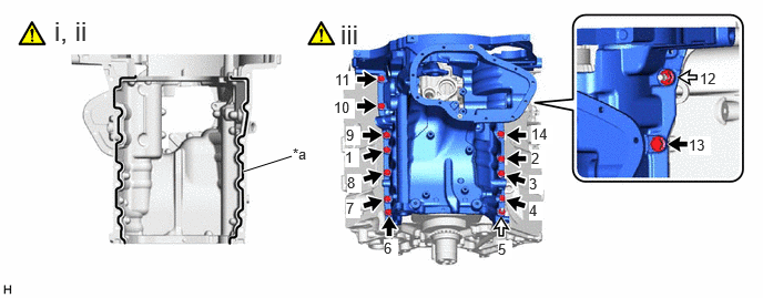
| *a | Standard Seal Packing Diameter 2.5 to 3.5 mm (0.0984 to 0.137 in.) |
- | - |
|
|
Bolt |

|
Nut |
Remove any remaining seal packing material and be careful not to drop any oil on the contact surfaces of the oil pan sub-assembly and cylinder block sub-assembly.
Apply seal packing in a continuous line as shown in the illustration.
- Seal packing:
-
Toyota Genuine Seal Packing Black, Three Bond 1207B or equivalent
- NOTICE:
-
·
Check and clean the bols and bolt holes.
·Clean and degrease the installation surface using non-residue solvent and brake cleaner.
·Install the oil pan sub-assembly within 3 minutes and tighten the bolts and nuts within 10 minutes after applying seal packing.
·Overlap the start and end area of each application approximately 10 mm.
Install the oil pan sub-assembly with the 12 bolts and 2 nuts in the order shown in the illustration.
- Torque:
- 24.5 N*m (250 kgf*cm, 18 ft.*lbf)
- NOTICE:
-
·
Do not add engine oil within 2 hours after installation.
·Do not start the engine for at least 2 hours after installation.
15413 8.INSTALL OIL PUMP OUTLET PIPE
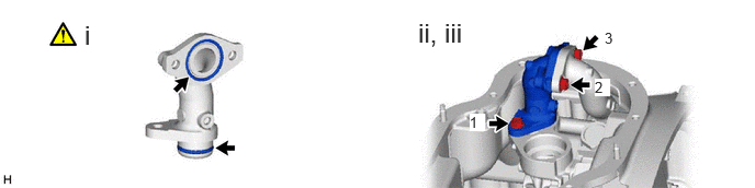
Install a new O-ring and apply engine oil.
Temporarily install the oil pump outlet pipe with the 3 bolts.
Tighten the 3 bolts in the order shown in the illustration.
- Torque:
- 10 N*m (102 kgf*cm, 7 ft.*lbf)
89491 9.INSTALL ENGINE OIL LEVEL SENSOR
|
|
Click here() |
15104 10.INSTALL OIL STRAINER SUB-ASSEMBLY
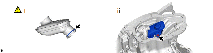
Apply engine oil to the O-ring.
Install the oil strainer sub-assembly with the bolt.
- Torque:
- 10 N*m (102 kgf*cm, 7 ft.*lbf)
12102A 11.INSTALL NO. 2 OIL PAN SUB-ASSEMBLY
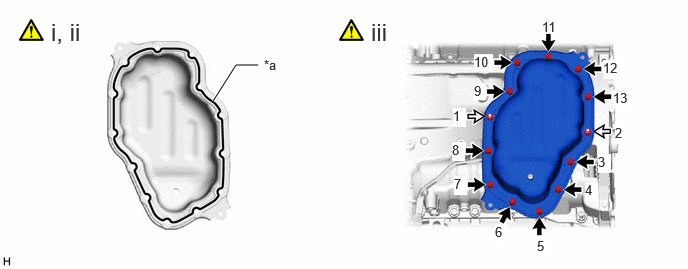
| *a | Standard Seal Packing Diameter 2.5 to 3.5 mm (0.0984 to 0.137 in.) |
- | - |
|
|
Bolt |
|
Nut |
Remove any remaining seal packing material and be careful not to drop any oil on the contact surfaces of the No. 2 oil pan sub-assembly and oil pan sub-assembly.
Apply seal packing in a continuous line as shown in the illustration.
- Seal packing:
-
Toyota Genuine Seal Packing Black, Three Bond 1207B or equivalent
- NOTICE:
-
·
Check and clean the bols and bolt holes.
·Clean and degrease the installation surface using non-residue solvent and brake cleaner.
·Install the No. 2 oil pan sub-assembly within 3 minutes and tighten the bolts and nuts within 10 minutes after applying seal packing.
·Overlap the start and end area of each application approximately 10 mm (0.394 in.)
Install the No. 2 oil pan sub-assembly with the 11 bolts and 2 nuts in the order shown in the illustration.
- Torque:
- 10 N*m (102 kgf*cm, 7 ft.*lbf)
- NOTICE:
-
·
Do not add engine oil within 2 hours after installation.
·Do not start the engine for at least 2 hours after installation.
12101A 12.INSTALL OIL PAN DRAIN PLUG
- Torque:
- 40 N*m (408 kgf*cm, 30 ft.*lbf)
12145 13.INSTALL NO. 2 OIL PAN COVER SILENCER
- Torque:
- 10 N*m (102 kgf*cm, 7 ft.*lbf)
15781 14.INSTALL NO. 1 OIL COOLER BRACKET
- Torque:
- 21 N*m (214 kgf*cm, 15 ft.*lbf)
12143 15.INSTALL OIL PAN COVER
- Torque:
- 10 N*m (102 kgf*cm, 7 ft.*lbf)
12140 16.INSTALL OIL PAN COVER
- Torque:
- 10 N*m (102 kgf*cm, 7 ft.*lbf)
17.INSTALL OIL PUMP CHAIN AND OIL PUMP DRIVE SHAFT SPROCKET
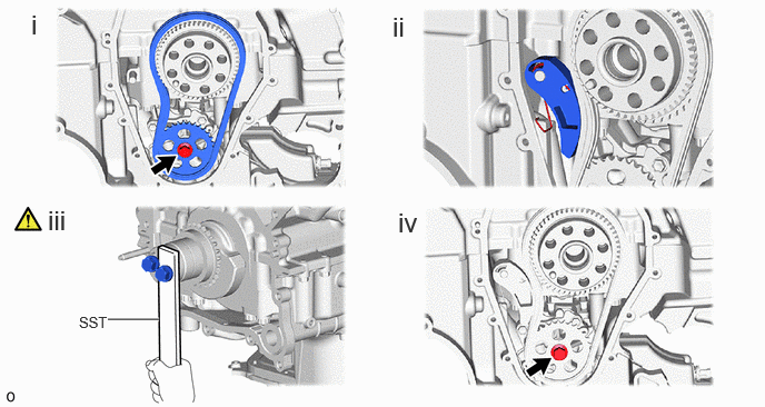
Install the oil pump chain and oil pump drive shaft sprocket, and temporarily install the bolt.
Install the chain tensioner plate.
Using SST and crankshaft set bolt, hold the crankshaft pulley sub-assembly.
- SST
-
09330-00021
Tighten the oil pump drive shaft sprocket bolt.
- Torque:
- 65 N*m (663 kgf*cm, 48 ft.*lbf)
11494 18.INSTALL OIL HOLE COVER PLATE
- Torque:
- 10 N*m (102 kgf*cm, 7 ft.*lbf)
13601A 19.INSTALL NO. 1 BALANCESHAFT SUB-ASSEMBLY
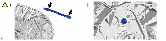
|
|
Apply Engine Oil | - | - |
Apply engine oil to the No. 1 balanceshaft sub-assembly.
Install the No. 1 balanceshaft sub-assembly.
13635 20.INSTALL BALANCESHAFT THRUST SPACER
- Torque:
- 10 N*m (102 kgf*cm, 7 ft.*lbf)
13632 21.INSTALL NO. 1 BALANCESHAFT DRIVEN GEAR
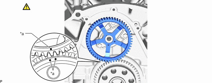
| *a | Timing Mark | - | - |
- HINT:
-
Align the timing marks as shown in the illustration to install the part.
13624 22.INSTALL REAR BALANCESHAFT WEIGHT
- Torque:
- 43 N*m (438 kgf*cm, 32 ft.*lbf)
11381A 23.INSTALL REAR ENGINE OIL SEAL
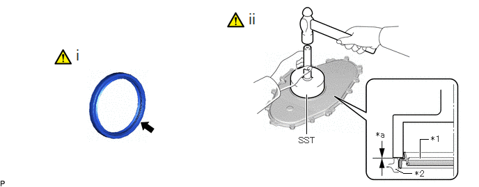
| *1 | Rear Engine Oil Seal | *2 | Rear Engine Oil Seal Retainer |
| *a | 0 to 2.0mm | - | - |
Apply MP grease to the lip of a new rear engine oil seal.
- NOTICE:
-
Do not allow MP grease to contact the dust seal.
Using SST and a hammer, tap in the rear engine oil seal to the rear engine oil seal retainer edge.
- SST
-
09223-56010
- Oil Seal Protrusion Height:
-
0 to 2.0 mm (0 to 0.0787 in.)
- NOTICE:
-
·
Do not tap the rear engine oil seal at an angle.
·Keep the lip free of foreign matter.
11381 24.INSTALL REAR ENGINE OIL SEAL RETAINER
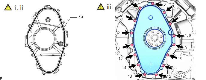
| *a | Standard Seal Packing Diameter 2.5 to 3.5 mm (0.0984 to 0.137 in.) |
- | - |
Remove any remaining seal packing material and be careful not to drop any oil on the contact surfaces of the rear engine oil seal retainer and cylinder block sub-assembly.
Apply seal packing in a continuous line as shown in the illustration.
- Seal packing:
-
Toyota Genuine Seal Packing Black, Three Bond 1207B or equivalent
- NOTICE:
-
·
Check and clean the bols and bolt holes.
·Clean and degrease the installation surface using non-residue solvent and brake cleaner.
·Install the rear engine oil seal retainer within 3 minutes and tighten the bolts within 10 minutes after applying seal packing.
·Overlap the start and end area of each application approximately 10 mm.
Install the rear engine oil seal retainer with the 15 bolts in the order shown in the illustration.
- Torque:
- 10 N*m (102 kgf*cm, 7 ft.*lbf)
- NOTICE:
-
·
Do not add engine oil within 2 hours after installation.
·Do not start the engine for at least 2 hours after installation.
11115 25.INSTALL CYLINDER HEAD GASKET
|
|
Click here() |
11101 26.INSTALL CYLINDER HEAD SUB-ASSEMBLY
|
|
Click here() |
11116 27.INSTALL NO. 2 CYLINDER HEAD GASKET
|
|
Click here() |
11102 28.INSTALL CYLINDER HEAD LH
|
|
Click here() |
13750 29.INSTALL VALVE LASH ADJUSTER ASSEMBLY (for Bank 1)
|
|
Click here() |
13716 30.INSTALL VALVE STEM CAP (for Bank 1)
|
|
Click here() |
13801 31.INSTALL NO. 1 VALVE ROCKER ARM SUB-ASSEMBLY (for Bank 1)
|
|
Click here() |
32.INSTALL NO. 2 CAMSHAFT BEARING CAP (for Bank 1)
33.INSTALL INTAKE CAMSHAFT SUB-ASSEMBLY RH AND EXHAUST CAMSHAFT SUB-ASSEMBLY RH (for Bank 1)
34.INSTALL NO. 1 CAMSHAFT BEARING CAP AND NO. 3 CAMSHAFT BEARING CAP (for Bank 1)
|
|
Click here() |
13523G 35.INSTALL CAMSHAFT TIMING SPROCKET (for Bank 1)
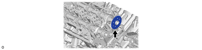
13522 36.INSTALL PUMP DRIVE SHAFT GEAR (for Bank 1)
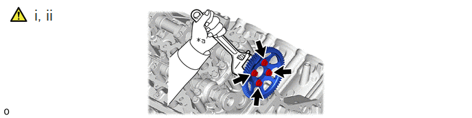
| *a | Hold | - | - |
Hold hexagonal portion of the exhaust camshaft sub-assembly RH with a wrench.
Install the pump drive shaft gear with the 3 bolts.
- Torque:
- 30 N*m (306 kgf*cm, 22 ft.*lbf)
13529G 37.INSTALL NO. 2 CAMSHAFT TIMING SPROCKET ASSEMBLY (for Bank 1)
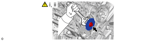
| *a | Hold | - | - |
Hold hexagonal portion of the intake camshaft sub-assembly RH with a wrench.
Install the No. 2 camshaft timing sprocket assembly with the bolt.
- Torque:
- 111 N*m (1132 kgf*cm, 82 ft.*lbf)
13750 38.INSTALL VALVE LASH ADJUSTER ASSEMBLY (for Bank 2)
|
|
Click here() |
13716 39.INSTALL VALVE STEM CAP (for Bank 2)
|
|
Click here() |
13801 40.INSTALL NO. 1 VALVE ROCKER ARM SUB-ASSEMBLY (for Bank 2)
|
|
Click here() |
41.INSTALL NO. 5 CAMSHAFT BEARING CAP (for Bank 2)
42.INSTALL INTAKE CAMSHAFT SUB-ASSEMBLY LH AND EXHAUST CAMSHAFT SUB-ASSEMBLY LH (for Bank 2)
43.INSTALL NO. 3 CAMSHAFT BEARING CAP AND NO. 4 CAMSHAFT BEARING CAP (for Bank 2)
|
|
Click here() |
13529G 44.INSTALL NO. 2 CAMSHAFT TIMING SPROCKET ASSEMBLY (for Bank 2)
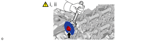
| *a | Hold | - | - |
Hold hexagonal portion of the intake camshaft sub-assembly LH with a wrench.
Install the No. 2 camshaft timing sprocket assembly with the bolt.
- Torque:
- 111 N*m (1132 kgf*cm, 82 ft.*lbf)
13523G 45.INSTALL CAMSHAFT TIMING SPROCKET (for Bank 2)
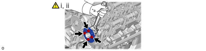
| *a | Hold | - | - |
Hold hexagonal portion of the exhaust camshaft sub-assembly LH with a wrench.
Install the camshaft timing sprocket with the 4 bolts.
- Torque:
- 30 N*m (306 kgf*cm, 22 ft.*lbf)
11310 46.INSTALL TIMING CHAIN COVER ASSEMBLY
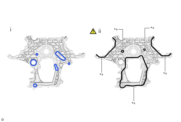
| *a | Standard Seal Packing Diameter 2.5 to 3.5 mm (0.0984 to 0.138 in.) |
- | - |

|
Seal Packing | - | - |
Install new gasket and new O-ring to the timing chain cover assembly.
Apply seal packing in a continuous line as shown in the illustration.
- Seal packing:
-
Toyota Genuine Seal Packing Black, Three Bond 1207B or equivalent
- NOTICE:
-
·
Check and clean the bols and bolt holes.
·Clean and degrease the installation surface using non-residue solvent and brake cleaner.
·Install the timing chain cover assembly within 3 minutes and tighten the bolts within 10 minutes after applying seal packing.
·Overlap the start and end area of each application approximately 10 mm.
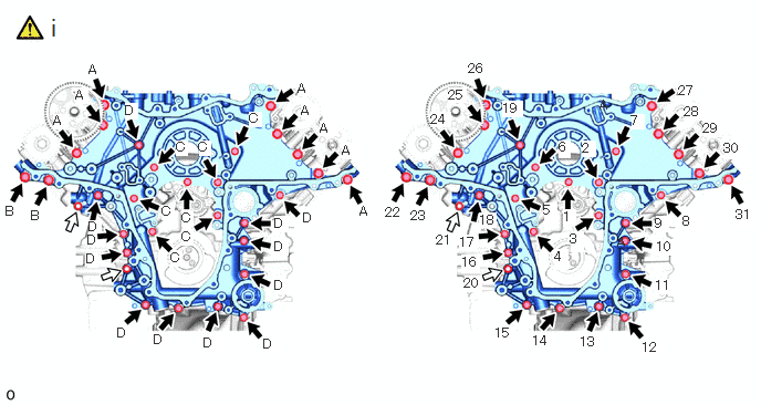
|
|
Bolt |
|
Nut |
Install the timing chain cover assembly with the new 22 bolts, 7 bolts and 2 nuts in the order shown in the illustration.
- Torque:
- Bolt A and Bolt B : 54 N*m (551 kgf*cm, 40 ft.*lbf)
- Bolt C, Bolt D and Nut : 29 N*m (296 kgf*cm, 21 ft.*lbf)
| Bolt | Bolt Length Beneath Head |
|---|---|
| Bolt A | 40 mm (1.57 in.) |
| Bolt B | 65 mm (2.56 in.) |
| Bolt C | 20 mm (0.787 in.) |
| Bolt D | 45 mm (1.77 in.) |
23243C 47.INSTALL FUEL PUMP MOTOR WIRE
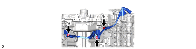
| *a | Bolt A | *b | Bolt B |
- Torque:
- Bolt A : 6.5 N*m (66 kgf*cm, 58 in.*lbf)
- Bolt B : 10 N*m (102 kgf*cm, 7 ft.*lbf)
22100 48.TEMPORARILY INJECTION OR SUPPLY PUMP ASSEMBLY
|
|
|
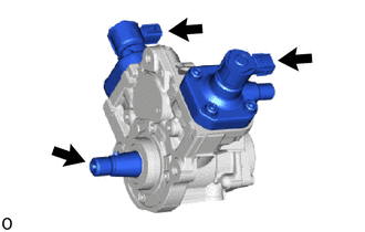
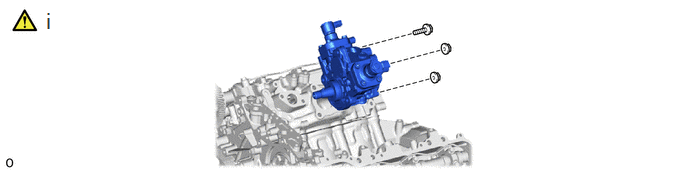
Temporarily install the injection or supply pump assembly with the bolt and 2 nuts.
- NOTICE:
-
Leave this temporarily installed. It will be tightened later.
13506A 49.INSTALL NO. 1 CHAIN SUB-ASSEMBLY AND SUPPLY PUMP SHAFT SPROCKET
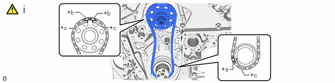
| *a | Mark Plate (Orange) | *b | Mark Plate (Yellow) |
| *c | Timing Mark | - | - |
Align the mark plate (orange) and mark plate (yellow) with the timing marks as shown in the illustration, and install the No. 1 chain sub-assembly and supply pump shaft sprocket.
13561 50.INSTALL NO. 1 CHAIN VIBRATION DAMPER
- Torque:
- 21 N*m (214 kgf*cm, 15 ft.*lbf)
13559 51.INSTALL CHAIN TENSIONER SLIPPER
13540 52.INSTALL NO. 1 CHAIN TENSIONER ASSEMBLY
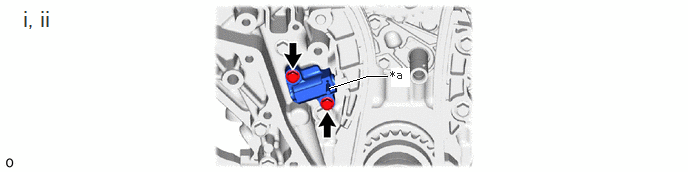
| *a | Pin | - | - |
Install the No. 1 chain tensioner assembly with the 2 bolts.
- Torque:
- 10 N*m (102 kgf*cm, 7 ft.*lbf)
Remove the pin from the No. 1 chain tensioner assembly.
11302 53.TEMPORARILY TIMING CHAIN OR BELT COVER SUB-ASSEMBLY
|
|
|
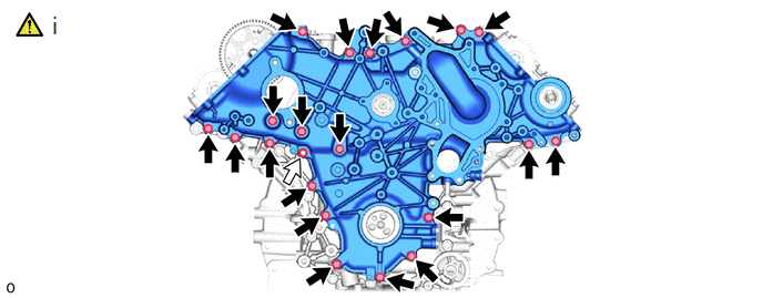
Temporarily install the timing chain or belt cover sub-assembly with the 20 bolts and nut.
- NOTICE:
-
Seat all bolts and nuts.
22100 54.INSTALL INJECTION OR SUPPLY PUMP ASSEMBLY
|
|
|
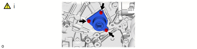
Align the hexagonal portion of SST with the supply pump drive coupling, install the SST to the timing chain or belt cover sub-assembly with the 3 bolts.
- SST
-
09241-11010
- Torque:
- 10 N*m (102 kgf*cm, 7 ft.*lbf)
- NOTICE:
-
Install SST with the bolts included with SST.
- HINT:
-
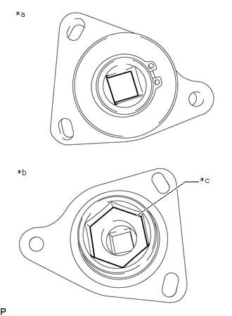 2.021,3.188 2.74,2.688 2.74,2.688 2.938,2.688 true 0.24,0.135 0.552,0.292 0.313,0.156 10 false *a 0.26,2.479 0.573,2.635 0.313,0.156 10 false *b 2.969,2.594 3.281,2.75 0.313,0.156 10 false *c
*a Engine Front Side *b Supply Pump Drive Coupling Side *c Hexagonal Portion
-
Make sure that the installation direction of SST is as shown in the illustration.
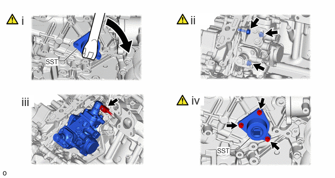
Turn the SST clockwise direction to install the injection or supply pump assembly to the timing chain or belt cover sub-assembly.
- SST
-
09241-11010
- HINT:
-
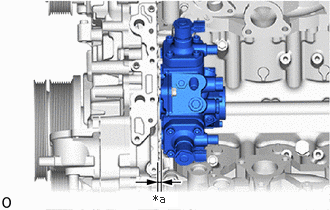 1.594,2 1.854,2.156 0.26,0.156 10 true *a
*a Gap
-
After tightening the part with SST, a gap of 2 to 3 mm (0.0787 to 0.118 in.) in A shown in the illustration is normal.
Install the bolt and 2 nuts.
- Torque:
- 21 N*m (214 kgf*cm, 15 ft.*lbf)
Connect the connector to the injection or supply pump assembly.
Remove the 3 bolts and SST.
- SST
-
09241-11010
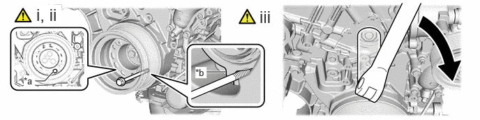
| *a | Service Hole | *b | Protrusion |
Align the service hole of the crankshaft pulley sub-assembly with the position as shown in the illustration.
Install a service bolt and fix the crankshaft pulley sub-assembly.
| Length | 120 mm (4.72 in.) or more |
| Diameter | 14 mm (0.551 in.) |
| Pitch | 1.5 |
| Thread Length | 70 mm (2.76 in.) or more |
- HINT:
-
The crankshaft pulley sub-assembly is fixed by hooking a service bolt on the convex part of the timing chain cover sub-assembly.
Using a 27 mm deep socket wrench, tighten the supply pump drive coupling.
- Torque:
- 137 N*m (1397 kgf*cm, 101 ft.*lbf)
- NOTICE:
-
If the supply pump shaft nut is tightened to the specified tightening torque or more, the chain sub-assembly may break.
Remove the crankshaft pully sub-assembly.
Click hereEngine / Hybrid System>F33A-FTV (ENGINE MECHANICAL)>ENGINE UNIT>DISASSEMBLY
Remove the timing chain or belt cover sub-assembly.
Click hereEngine / Hybrid System>F33A-FTV (ENGINE MECHANICAL)>ENGINE UNIT>DISASSEMBLY
11324 55.INSTALL TIMING CHAIN COVER PLATE
|
|
Click here() |
13507 56.INSTALL NO. 2 CHAIN SUB-ASSEMBLY
|
|
|
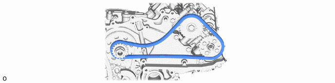
- HINT:
-
Align the mark plate and timing mark and install the part as shown in the illustration.
-
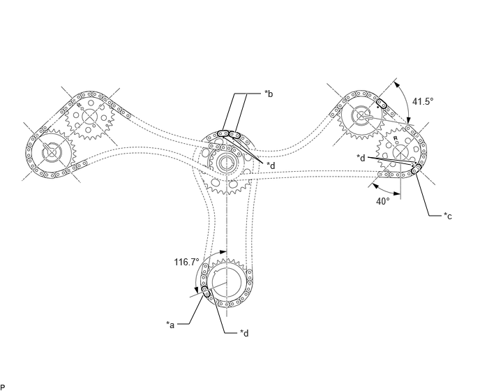 2.646,4.833 2.823,4.833 2.823,4.833 3.031,4.406 true 3.156,4.333 3.354,4.969 3.354,4.969 3.542,4.969 true 6.135,2.458 5.49,2.344 5.49,2.344 6.188,2.417 true 6.208,2.583 6.406,3.219 6.406,3.219 6.594,3.219 true 3.49,2.073 3.927,2.438 3.927,2.438 3.344,2.052 true 3.323,1.938 3.5,1.396 3.5,1.396 3.896,1.396 true 3.51,1.979 3.688,1.396 true 2.479,4.76 2.729,5.031 0.25,0.271 10 false *a 3.948,1.313 4.25,1.521 0.302,0.208 10 false *b 3.583,4.885 3.875,5.073 0.292,0.188 10 false *d 6.156,1.427 6.823,1.948 0.667,0.521 10 false 41.5° 2.594,3.823 3.344,4.302 0.75,0.479 10 false 116.7° 5.615,2.917 5.927,3.156 0.313,0.24 10 false 40° 5.323,2.271 5.615,2.458 0.292,0.188 10 false *d 6.625,3.135 6.927,3.323 0.302,0.188 10 false *c 3.979,2.385 4.271,2.573 0.292,0.188 10 false *d
*a Mark Plate (Orange) *b Mark Plate (Yellow) *c Mark Plate (Pink) *d Timing Mark
13563 57.INSTALL NO. 3 CHAIN VIBRATION DAMPER
- Torque:
- 21 N*m (214 kgf*cm, 15 ft.*lbf)
13559F 58.INSTALL CHAIN TENSIONER SLIPPER LH
13560A 59.INSTALL NO. 3 CHAIN TENSIONER ASSEMBLY
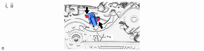
| *a | Pin | - | - |
Install the No. 3 chain tensioner assembly with the 2 bolts.
- Torque:
- 10 N*m (102 kgf*cm, 7 ft.*lbf)
Remove the pin from the No. 3 chain tensioner assembly.
13507 60.INSTALL NO. 2 CHAIN SUB-ASSEMBLY
|
|
|
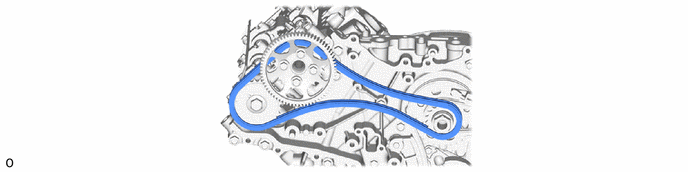
- HINT:
-
Align the mark plate and timing mark and install the part as shown in the illustration
-
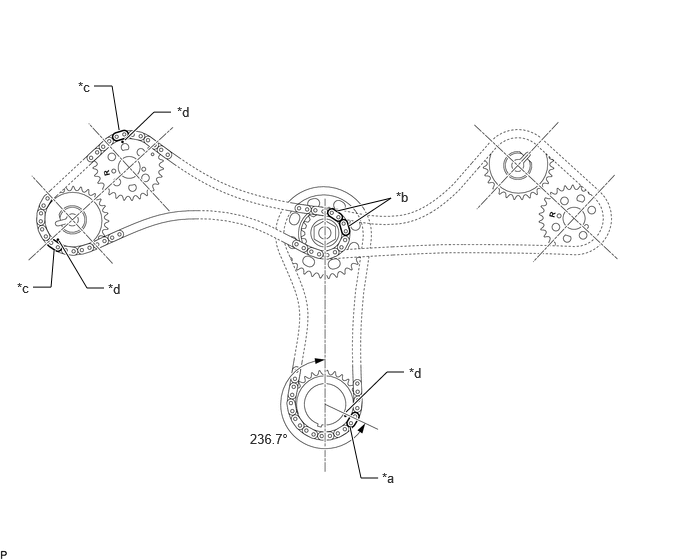 0.979,0.896 1.167,0.896 1.167,0.896 1.24,1.354 true 0.344,2.99 0.531,2.99 0.531,2.99 0.563,2.604 true 0.615,2.51 0.906,3 0.906,3 1.083,3 true 1.302,1.458 1.604,1.167 1.604,1.167 1.781,1.167 true 3.51,2.198 4.073,2.063 4.073,2.063 3.635,2.354 true 3.604,4.292 4.031,3.875 4.031,3.875 4.208,3.875 true 3.646,4.448 3.76,4.979 3.76,4.979 3.938,4.979 true 3.979,4.896 4.292,5.104 0.313,0.208 10 false *a 4.125,1.969 4.396,2.156 0.271,0.188 10 false *b 0.813,0.823 1.125,1.031 0.313,0.208 10 false *c 1.125,2.927 1.417,3.146 0.292,0.219 10 false *d 0.177,2.917 0.49,3.125 0.313,0.208 10 false *c 1.844,1.083 2.135,1.302 0.292,0.219 10 false *d 2.604,4.49 3.594,5.25 0.99,0.76 10 false 236.7° 4.26,3.802 4.552,4.021 0.292,0.219 10 false *d
*a Mark Plate (Orange) *b Mark Plate (Yellow) *c Mark Plate (Pink) *d Timing Mark
13562 61.INSTALL NO. 2 CHAIN VIBRATION DAMPER
- Torque:
- 21 N*m (214 kgf*cm, 15 ft.*lbf)
13559E 62.INSTALL CHAIN TENSIONER SLIPPER RH
13550 63.INSTALL NO. 2 CHAIN TENSIONER ASSEMBLY
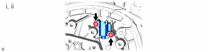
| *a | Pin | - | - |
Install the No. 2 chain tensioner assembly with the 2 bolts.
- Torque:
- 10 N*m (102 kgf*cm, 7 ft.*lbf)
Remove the pin from the No. 2 chain tensioner assembly.
64.SET NO. 1 CYLINDER TO TDC/COMPRESSION
|
|
Click here() |
11302A 65.INSTALL TIMING CHAIN OR BELT COVER OIL SEAL
|
|
Click here() |
11302 66.INSTALL TIMING CHAIN OR BELT COVER SUB-ASSEMBLY
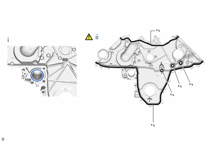
| *a | Standard Seal Packing Diameter 2.5 to 3.5 mm (0.0984 to 0.138 in.) |
- | - |
|
|
Seal Packing | - | - |
Install a new O-ring to the timing chain or belt cover sub-assembly.
Apply seal packing in a continuous line as shown in the illustration.
- Seal packing:
-
Toyota Genuine Seal Packing Black, Three Bond 1207B or equivalent
- NOTICE:
-
·
Check and clean the bols and bolt holes.
·Clean and degrease the installation surface using non-residue solvent and brake cleaner.
·Install the timing chain or belt cover sub-assembly within 3 minutes and tighten the bolts within 10 minutes after applying seal packing.
·Overlap the start and end area of each application approximately 10 mm.
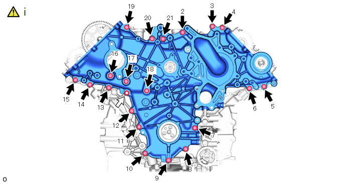
|
|
Bolt |
|
Nut |
Install the timing chain or belt cover sub-assembly with the 20 bolts and nut in the order shown in the illustration.
- Torque:
- 24.5 N*m (250 kgf*cm, 18 ft.*lbf)
16100 67.INSTALL ENGINE WATER PUMP ASSEMBLY
|
|
Click here() |
11339D 68.INSTALL NO. 2 TIMING CHAIN COVER INSULATOR
- Torque:
- 10 N*m (102 kgf*cm, 7 ft.*lbf)
13408 69.INSTALL CRANKSHAFT PULLEY SUB-ASSEMBLY
|
|
Click here() |
11211 70.INSTALL CYLINDER HEAD COVER RH
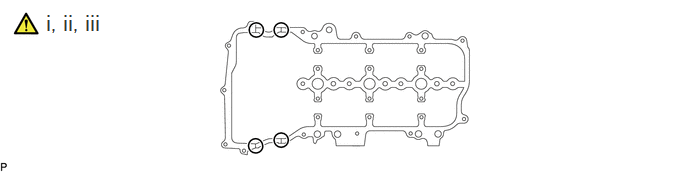
Before applying seal packing black, cleanly remove any old sealant sticking to the part to be sealed.
Remove any remaining seal packing material and be careful not to drop any oil on the contact surfaces of the cylinder head sub-assembly, timing chain cover assembly and cylinder head cover RH.
Apply seal packing as shown in the illustration.
- NOTICE:
-
·
Remove any oil from the contact surface.
·Install the cylinder head cover RH within 3 minutes and tighten the bolts within 10 minutes after applying seal packing.
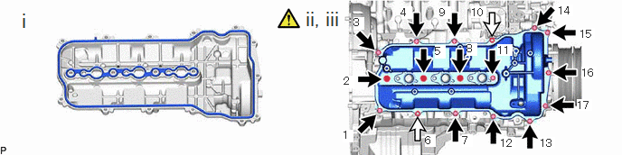
|
|
Bolt |
|
Nut |
Install new cylinder head cover gasket and new No. 3 cylinder head cover gasket to the cylinder head cover RH.
Degrease the threads of the 15 cylinder head cover installation bolts.
Install the cylinder head cover RH with the 15 bolts and 2 nuts.
- Torque:
- 10 N*m (102 kgf*cm, 7 ft.*lbf)
- NOTICE:
-
Do not start the engine for at least 2 hours after installation.
11224 71.INSTALL CYLINDER HEAD COVER SILENCER
- Torque:
- 5.0 N*m (51 kgf*cm, 44 in.*lbf)
23243C 72.CONNECT FUEL PUMP MOTOR WIRE
- Torque:
- 10 N*m (102 kgf*cm, 7 ft.*lbf)
23764A 73.INSTALL NO. 4 NOZZLE LEAKAGE PIPE
- Torque:
- 21 N*m (214 kgf*cm, 15 ft.*lbf)
12270K 74.INSTALL OIL SEPARATOR ASSEMBLY
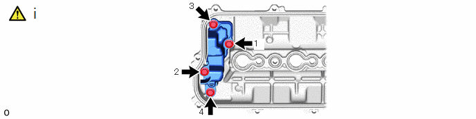
Install the oil separator assembly with the 4 bolts in the order shown in the illustration.
- Torque:
- 10 N*m (102 kgf*cm, 7 ft.*lbf)
11212B 75.INSTALL CYLINDER HEAD COVER LH
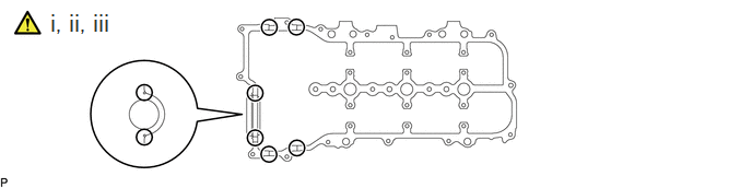
Before applying seal packing black, cleanly remove any old sealant sticking to the part to be sealed.
Remove any remaining seal packing material and be careful not to drop any oil on the contact surfaces of the cylinder head LH, timing chain cover assembly and cylinder head cover LH.
Apply seal packing as shown in the illustration.
- NOTICE:
-
·
Remove any oil from the contact surface.
·Install the cylinder head cover LH within 3 minutes and tighten the bolts within 10 minutes after applying seal packing.
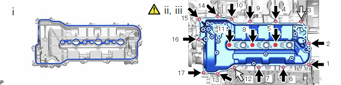
|
|
Bolt |
|
Nut |
Install new No. 1 cylinder head cover gasket LH and new No. 4 cylinder head cover gasket to the cylinder head cover LH.
Degrease the threads of the 15 cylinder head cover installation bolts.
Install the cylinder head cover LH with the 15 bolts and 2 nuts.
- Torque:
- 10 N*m (102 kgf*cm, 7 ft.*lbf)
- NOTICE:
-
Do not start the engine for at least 2 hours after installation.
11225 76.INSTALL CYLINDER HEAD COVER LH SILENCER
- Torque:
- 5.0 N*m (51 kgf*cm, 44 in.*lbf)
12277 77.INSTALL OIL SEPARATOR HOLDER
- Torque:
- 10 N*m (102 kgf*cm, 7 ft.*lbf)
23211M 78.INSTALL FUEL PIPE BRACKET
- Torque:
- 10 N*m (102 kgf*cm, 7 ft.*lbf)
29300 79.INSTALL VACUUM PUMP ASSEMBLY
|
|
Click here() |
21989B 80.INSTALL PLATE INSULATOR
16293 81.INSTALL NO. 10 WATER BY-PASS HOSE
16571E 82.INSTALL WATER HOSE
11336B 83.INSTALL TIMING CHAIN COVER INSULATOR
16307A 84.INSTALL FAN BRACKET SUB-ASSEMBLY
12511C 85.INSTALL GENERATOR BRACKET
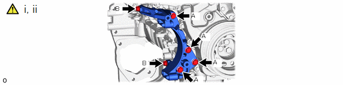
Temporarily install the generator bracket with the 6 bolts.
Tighten the 6 bolts, install the generator bracket.
- Torque:
- 43 N*m (438 kgf*cm, 32 ft.*lbf)
- NOTICE:
-
Tighten the order of (A) and (B).
16331A 86.INSTALL THERMOSTAT
|
|
Click here() |
16321 87.INSTALL WATER INLET
|
|
Click here() |
16603B 88.INSTALL IDLER PULLEY SUB-ASSEMBLY
- Torque:
- 43 N*m (438 kgf*cm, 32 ft.*lbf)
16620D 89.INSTALL V-RIBBED BELT TENSIONER ASSEMBLY
11415A 90.INSTALL CYLINDER BLOCK WATER DRAIN COCK PLUG
- Torque:
- 25 N*m (255 kgf*cm, 18 ft.*lbf)
88431 91.INSTALL NO. 1 COMPRESSOR MOUNTING BRACKET
- Torque:
- 21 N*m (214 kgf*cm, 15 ft.*lbf)
15674 92.INSTALL OIL FILTER RECEIVER
- Torque:
- 10 N*m (102 kgf*cm, 7 ft.*lbf)
15601 93.INSTALL OIL FILTER SUB-ASSEMBLY
83520 94.INSTALL OIL PRESSURE SENDER GAGE ASSEMBLY
|
|
Click here() |
11401G 95.INSTALL CRANKSHAFT POSITION SENSOR
|
|
Click here() |
12581A 96.INSTALL NO. 1 CYLINDER BLOCK INSULATOR
- Torque:
- 10 N*m (102 kgf*cm, 7 ft.*lbf)
12315A 97.INSTALL ENGINE MOUNTING BRACKET RH
- Torque:
- 80 N*m (816 kgf*cm, 59 ft.*lbf)
98.INSTALL NO. 2 WIRING HARNESS CLAMP BRACKET
- Torque:
- 10 N*m (102 kgf*cm, 7 ft.*lbf)
12582A 99.INSTALL NO. 2 CYLINDER BLOCK INSULATOR
12325A 100.INSTALL ENGINE MOUNTING BRACKET LH
- Torque:
- 80 N*m (816 kgf*cm, 59 ft.*lbf)
16207 101.INSTALL NO. 2 WATER BY-PASS PIPE SUB-ASSEMBLY
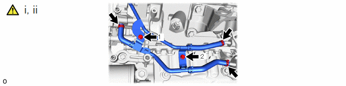
Connect the 3 hoses and slide the clip to secure it.
Install the No. 2 water by-pass pipe sub-assembly with the 2 bolts in the order shown in the illustration.
- Torque:
- 10 N*m (102 kgf*cm, 7 ft.*lbf)
27148D 102.INSTALL NO. 1 CONNECTING WIRE
15710 103.INSTALL OIL COOLER ASSEMBLY
17111 104.INSTALL INTAKE MANIFOLD
105.INSTALL NO. 2 WIRE HARNESS CLAMP
17112 106.INSTALL NO. 2 INTAKE MANIFOLD
11452 107.INSTALL ENGINE OIL LEVEL DIPSTICK GUIDE
19850 108.INSTALL GLOW PLUG ASSEMBLY
|
|
Click here() |
23811K 109.INSTALL GASKET
23811G 110.INSTALL NO. 1 FUEL PIPE
|
|
Click here() |
23801N 111.INSTALL GASKET
23765 112.INSTALL NO. 5 NOZZLE LEAKAGE PIPE
|
|
Click here() |
23812D 113.INSTALL NO. 2 FUEL PIPE
15471 114.INSTALL TURBO OIL INLET GASKET
17293 115.INSTALL TURBOCHARGER STAY
16343 116.INSTALL WATER OUTLET HOUSING GASKET
16331 117.INSTALL WATER OUTLET
15776A 118.CONNECT NO. 4 OIL COOLER HOSE
16341 119.INSTALL WATER OUTLET GASKET
16335B 120.INSTALL NO. 2 WATER OUTLET PIPE
|
|
Click here() |
23300D 121.INSTALL DIESEL FUEL FILTER ASSEMBLY
23815D 122.INSTALL NO. 3 FUEL PIPE
23816 123.INSTALL NO. 4 FUEL PIPE
23763 124.INSTALL NO. 3 NOZZLE LEAKAGE PIPE
23810A 125.INSTALL COMMON RAIL ASSEMBLY (for Bank 1)
23804H 126.INSTALL FUEL PIPE GASKET
23805B 127.INSTALL NO. 5 FUEL PIPE SUB-ASSEMBLY
|
|
Click here() |
23802F 128.CONNECT FUEL HOSE
23704 129.INSTALL NO. 4 INJECTION PIPE SUB-ASSEMBLY
|
|
Click here() |
16341 130.INSTALL WATER OUTLET GASKET
16332 131.INSTALL NO. 1 WATER OUTLET PIPE
|
|
Click here() |
23820A 132.INSTALL COMMON RAIL ASSEMBLY (for Bank 2)
23706 133.INSTALL NO. 6 INJECTION PIPE SUB-ASSEMBLY
|
|
Click here() |
23705 134.INSTALL NO. 5 INJECTION PIPE SUB-ASSEMBLY
|
|
Click here() |
22815A 135.INSTALL INJECTION PUMP INSULATOR
23682 136.INSTALL NOZZLE HOLDER GASKET (for Bank 2)
11176 137.INSTALL INJECTION NOZZLE SEAT (for Bank 2)
138.INSTALL O-RING (for Bank 2)
23670 139.INSTALL INJECTOR ASSEMBLY (for Bank 2)
|
|
·
Temporarily install injector assembly (for Bank 2) Click here(
·
Install injector assembly (for Bank 2) Click here( |
140.INSTALL INJECTION PIPE SUB-ASSEMBLY (for Bank 2)
|
|
·
Temporarily install injection pipe sub-assembly (for Bank 2) Click here(
·
Install injection pipe sub-assembly (for Bank 2) Click here( |
23760A 141.INSTALL GASKET
23762B 142.INSTALL NO. 2 NOZZLE LEAKAGE PIPE
23682 143.INSTALL NOZZLE HOLDER GASKET (for Bank 1)
11176 144.INSTALL INJECTION NOZZLE SEAT (for Bank 1)
145.INSTALL O-RING (for Bank 1)
23670 146.INSTALL INJECTOR ASSEMBLY (for Bank 1)
|
|
·
Temporarily install injector assembly (for Bank 1) Click here(
·
Install injector assembly (for Bank 1) Click here( |
147.INSTALL INJECTION PIPE SUB-ASSEMBLY (for Bank 1)
|
|
·
Temporarily install injection pipe sub-assembly (for Bank 1) Click here(
·
Install injection pipe sub-assembly (for Bank 1) Click here( |
23760A 148.INSTALL GASKET
23761A 149.INSTALL NO. 1 NOZZLE LEAKAGE PIPE