F33A-FTV FUEL FUEL INJECTOR INSTALLATION
CAUTION / NOTICE / HINT
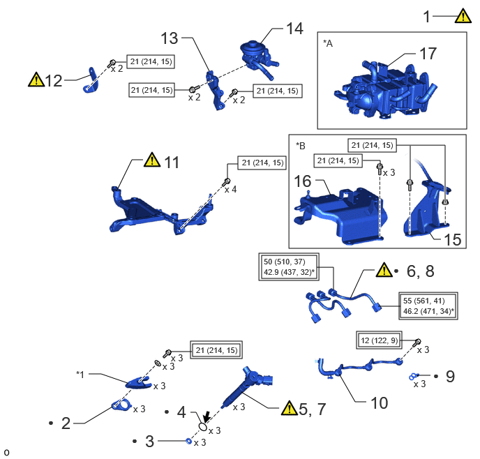
| Procedure | Part Name Code |

|

|

|
|
|---|---|---|---|---|---|
| 1 | PRECAUTION FOR WORK | - | ( ) |
- | - |
| 2 | NOZZLE HOLDER GASKET | 23682 | - | - | - |
| 3 | INJECTION NOZZLE SEAT | 11176 | - | - | - |
| 4 | O-RING | - | - | - | - |
| 5 | TEMPORARILY INSTALL INJECTOR ASSEMBLY | 23670 | () |
- | - |
| 6 | TEMPORARILY INSTALL INJECTION PIPE SUB-ASSEMBLY | - | () |
- | - |
| 7 | INSTALL INJECTOR ASSEMBLY | 23670 | - | - | - |
| 8 | INSTALL INJECTION PIPE SUB-ASSEMBLY | - | () |
- | - |
| 9 | GASKET | 23760A | - | - | - |
| 10 | NO. 2 NOZZLE LEAKAGE PIPE | 23762B | - | - | - |
| 11 | NO. 1 EGR COOLER BRACKET | 25687 | () |
- | - |
| 12 | NO. 2 TURBOCHARGER STAY | 17297 | () |
- | - |
| 13 | FUEL SUPPORT | 23849 | - | - | - |
| 14 | FUEL PRIMING PUMP ASSEMBLY | 23100Y | - | - | - |
| 15 | NO. 2 CLAMP STAY | 17561H | - | - | - |
| 16 | CLAMP STAY | 17561G | - | - | - |
| 17 | EGR COOLER ASSEMBLY | - | - | - | - |
| *A | w/ EGR System | *B | w/o EGR System |
| *1 | NO. 1 NOZZLE HOLDER CLAMP | - | - |

|
Tightening torque for "Major areas involving basic vehicle performance such as moving/turning/stopping": N*m (kgf*cm, ft.*lbf) |

|
N*m (kgf*cm, ft.*lbf): Specified torque |
| * | For use with SST or union nut wrench | ● | Non-reusable part |

|
Engine oil | - | - |
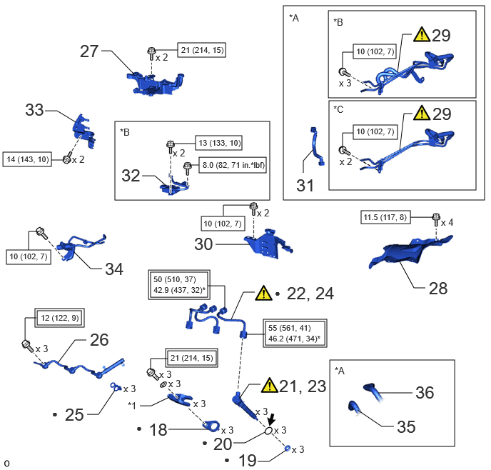
| Procedure | Part Name Code |
|
|
|
|
|---|---|---|---|---|---|
| 18 | NOZZLE HOLDER GASKET | 23682 | - | - | - |
| 19 | INJECTION NOZZLE SEAT | 11176 | - | - | - |
| 20 | O-RING | - | - | - | - |
| 21 | TEMPORARILY INSTALL INJECTOR ASSEMBLY | 23670 | () |
- | - |
| 22 | TEMPORARILY INSTALL INJECTION PIPE SUB-ASSEMBLY | - | () |
- | - |
| 23 | INSTALL INJECTOR ASSEMBLY | 23670 | - | - | - |
| 24 | INSTALL INJECTION PIPE SUB-ASSEMBLY | - | () |
- | - |
| 25 | GASKET | 23760A | - | - | - |
| 26 | NO. 1 NOZZLE LEAKAGE PIPE | 23761A | - | - | - |
| 27 | NO. 2 INTERCOOLER SUPPORT BRACKET | 17946 | - | - | - |
| 28 | INTAKE PIPE INSULATOR | 17117A | - | - | - |
| 29 | NO. 3 WATER BY-PASS PIPE SUB-ASSEMBLY | 16206B | () |
- | - |
| 30 | TURBO INSULATOR STAY | 17273A | - | - | - |
| 31 | FUEL TUBE SUB-ASSEMBLY | 23901H | - | - | - |
| 32 | NO. 1 NITROGEN OXIDES SENSOR | 89463C | - | - | - |
| 33 | TURBO WATER PIPE STAY | 162A1A | - | - | - |
| 34 | NO. 2 VACUUM SWITCHING VALVE ASSEMBLY | 25860D | - | - | - |
| 35 | NO. 17 WATER BY-PASS HOSE | 1629D | - | - | - |
| 36 | NO. 15 WATER BY-PASS HOSE | 1629B | - | - | - |
| *A | w/ DPF | *B | w/ Urea SCR System |
| *C | w/o Urea SCR System | - | - |
| *1 | NO. 1 NOZZLE HOLDER CLAMP | - | - |
|
|
Tightening torque for "Major areas involving basic vehicle performance such as moving/turning/stopping": N*m (kgf*cm, ft.*lbf) |
|
N*m (kgf*cm, ft.*lbf): Specified torque |
| * | For use with SST or union nut wrench | ● | Non-reusable part |
|
|
Engine oil | - | - |
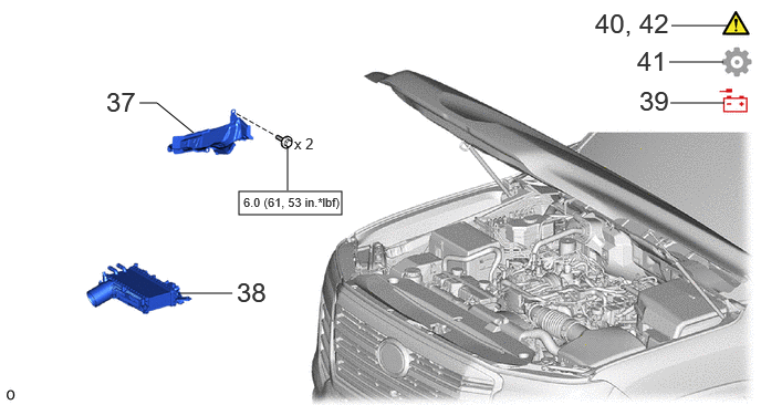
| Procedure | Part Name Code |
|
|
|
|
|---|---|---|---|---|---|
| 37 | REAR ENGINE SIDE UNDER COVER ASSEMBLY RH | 51460C | - | - | - |
| 38 | INTERCOOLER ASSEMBLY | 17940D | - | - | - |
| 39 | CONNECT CABLE TO NEGATIVE BATTERY TERMINAL | - | - | - | - |
| 40 | BLEED AIR FROM FUEL SYSTEM | - | () |
- | - |
| 41 | INITIALIZATION AFTER RECONNECTING BATTERY TERMINAL | - | - | - | () |
| 42 | INSPECT FOR FUEL LEAK | - | () |
- | - |
|
|
N*m (kgf*cm, ft.*lbf): Specified torque | - | - |
PROCEDURE

 1. PRECAUTION FOR WORK
|
|
|
23682 2.INSTALL NOZZLE HOLDER GASKET (for Bank 2)
11176 3.INSTALL INJECTION NOZZLE SEAT (for Bank 2)
4.INSTALL O-RING (for Bank 2)
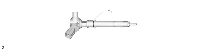
| *a | Apply engine oil | - | - |
23670 5.TEMPORARILY INSTALL INJECTOR ASSEMBLY (for Bank 2)
|
|
|
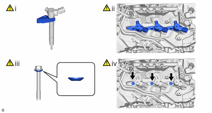
Set the No. 1 nozzle holder clamp to each injector assembly.
Install the 3 injector assemblies to the cylinder head LH.
- NOTICE:
-
Fit the injector assembly to the injection nozzle seats.
Set the washer to each bolt.
- NOTICE:
-
Pay attention to the mounting orientation (beveled edge) of the washer.
Install the 3 bolts.
- Torque:
- 2.0 N*m (20 kgf*cm, 18 in.*lbf)
- NOTICE:
-
·
Tighten to the specified torque to prevent fuel leakage due to poor alignment.
·Make sure that the bolt and No. 1 nozzle holder clamp are not at an angle.
6.TEMPORARILY INSTALL INJECTION PIPE SUB-ASSEMBLY (for Bank 2)
|
|
|
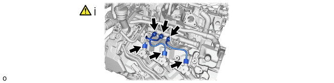
Temporarily install 3 new injection pipe sub-assemblies to the injector assembly and common rail assembly with the 6 union nuts.
- HINT:
-
Install the union nut by hand until all of the threads make contact.
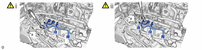
| *a | Torque Wrench Fulcrum Length | - | - |
Using SST, tighten the union nut on the injector assembly side of the injection pipe sub-assembly.
- SST
-
09268-78010
- Torque:
- Specified tightening torque:
-
10 N*m (102 kgf*cm, 7 ft.*lbf)
- HINT:
-
·
Calculate the torque wrench reading when changing the fulcrum length of the torque wrench.
Click hereGeneral>INTRODUCTION>REPAIR INSTRUCTION>PRECAUTION
·When using SST (fulcrum length of 34.5 mm (1.36 in.)) + torque wrench (fulcrum length of 162 mm (6.38 in.)): 8.2 N*m (84 kgf*cm, 73 in.*lbf)
Using a 17 mm union nut wrench, tighten the union nut on the common rail assembly side of the injection pipe sub-assembly.
- Torque:
- Specified tightening torque:
-
10 N*m (102 kgf*cm, 7 ft.*lbf)
- HINT:
-
·
Calculate the torque wrench reading when changing the fulcrum length of the torque wrench.
Click hereGeneral>INTRODUCTION>REPAIR INSTRUCTION>PRECAUTION
·When using a union nut wrench (fulcrum length of 30 mm (1.18 in.)) + torque wrench (fulcrum length of 162 mm (6.38 in.)): 8.4 N*m
23670 7.INSTALL INJECTOR ASSEMBLY (for Bank 2)
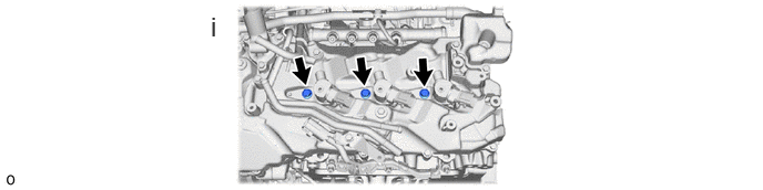
Tighten the 3 bolts.
- Torque:
- 21 N*m (214 kgf*cm, 15 ft.*lbf)
8.INSTALL INJECTION PIPE SUB-ASSEMBLY (for Bank 2)
| *a | Torque Wrench Fulcrum Length | - | - |
Using SST, tighten the union nut on the injector assembly side of the injection pipe sub-assembly.
- SST
-
09268-78010
- Torque:
- Specified tightening torque:
-
55 N*m (561 kgf*cm, 41 ft.*lbf)
- HINT:
-
·
Calculate the torque wrench reading when changing the fulcrum length of the torque wrench.
Click hereGeneral>INTRODUCTION>REPAIR INSTRUCTION>PRECAUTION
·When using SST (fulcrum length of 34.5 mm (1.36 in.)) + torque wrench (fulcrum length of 180 mm (7.09 in.)): 46.2 N*m (471 kgf*cm, 34 ft.*lbf)
Using a 17 mm union nut wrench, tighten the union nut on the common rail assembly side of the injection pipe sub-assembly.
- Torque:
- Specified tightening torque:
-
50 N*m (510 kgf*cm, 37 ft.*lbf)
- HINT:
-
·
Calculate the torque wrench reading when changing the fulcrum length of the torque wrench.
Click hereGeneral>INTRODUCTION>REPAIR INSTRUCTION>PRECAUTION
·When using a union nut wrench (fulcrum length of 30 mm (1.18 in.)) + torque wrench (fulcrum length of 180 mm (7.09 in.)): 42.9 N*m (437 kgf*cm, 32 ft.*lbf)
23760A 9.INSTALL GASKET
23762B 10.INSTALL NO. 2 NOZZLE LEAKAGE PIPE
- Torque:
- 12 N*m (122 kgf*cm, 9 ft.*lbf)
25687 11.INSTALL NO. 1 EGR COOLER BRACKET
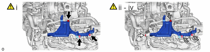

|
Bolt A |

|
Bolt B |
Temporarily install the No. 1 EGR cooler bracket to the cylinder head cover LH with the 3 bolts.
Install the bolt A.
- Torque:
- 5.0 N*m (51 kgf*cm, 44 in.*lbf)
Tighten the bolt B.
- Torque:
- 21 N*m (214 kgf*cm, 15 ft.*lbf)
Tighten the bolt A.
- Torque:
- 21 N*m (214 kgf*cm, 15 ft.*lbf)
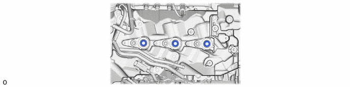
17297 12.INSTALL NO. 2 TURBOCHARGER STAY
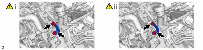
Temporarily install the No. 2 turbocharger stay to the No. 2 turbocharger sub-assembly and cylinder head cover LH with the 2 bolts.
Tighten the 2 bolts in the order shown in the illustration.
- Torque:
- 21 N*m (214 kgf*cm, 15 ft.*lbf)
23849 13.INSTALL FUEL SUPPORT
- Torque:
- 21 N*m (214 kgf*cm, 15 ft.*lbf)
23100Y 14.CONNECT FUEL PRIMING PUMP ASSEMBLY
- Torque:
- 21 N*m (214 kgf*cm, 15 ft.*lbf)
17561H 15.INSTALL NO. 2 CLAMP STAY (w/o EGR System)
- Torque:
- 21 N*m (214 kgf*cm, 15 ft.*lbf)
17561G 16.INSTALL CLAMP STAY (w/o EGR System)
- Torque:
- 21 N*m (214 kgf*cm, 15 ft.*lbf)
17.INSTALL EGR COOLER ASSEMBLY (w/ EGR System)
23682 18.INSTALL NOZZLE HOLDER GASKET (for Bank 1)
11176 19.INSTALL INJECTION NOZZLE SEAT (for Bank 1)
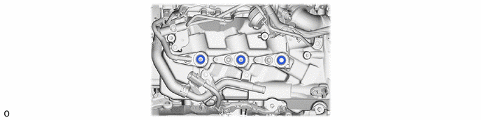
20.INSTALL O-RING (for Bank 1)
| *a | Apply engine oil | - | - |
23670 21.TEMPORARILY INSTALL INJECTOR ASSEMBLY (for Bank 1)
|
|
|
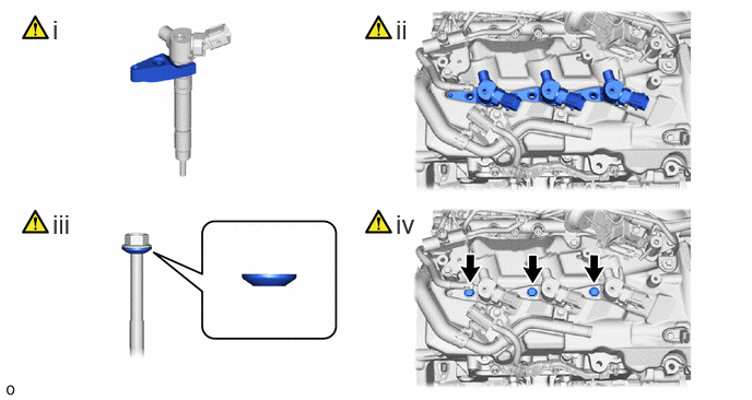
Set the No. 1 nozzle holder clamp to each injector assembly.
Install the 3 injector assemblies to the cylinder head sub-assembly.
- NOTICE:
-
Fit the injector assembly to the injection nozzle seats.
Set the washer to each bolt.
- NOTICE:
-
Pay attention to the mounting orientation (beveled edge) of the washer.
Install the 3 bolts.
- Torque:
- 2.0 N*m (20 kgf*cm, 18 in.*lbf)
- NOTICE:
-
·
Tighten to the specified torque to prevent fuel leakage due to poor alignment.
·Make sure that the bolt and No. 1 nozzle holder clamp are not at an angle.
22.TEMPORARILY INSTALL INJECTION PIPE SUB-ASSEMBLY (for Bank 1)
|
|
|
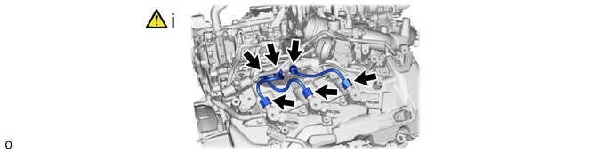
Temporarily install 3 new injection pipe sub-assemblies to the injector assembly and common rail assembly with the 6 union nuts.
- HINT:
-
Install the union nut by hand until all of the threads make contact.
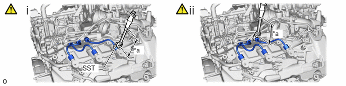
| *a | Torque Wrench Fulcrum Length | - | - |
Using SST, tighten the union nut on the injector assembly side of the injection pipe sub-assembly.
- SST
-
09268-78010
- Torque:
- Specified tightening torque:
-
10 N*m (102 kgf*cm, 7 ft.*lbf)
- HINT:
-
·
Calculate the torque wrench reading when changing the fulcrum length of the torque wrench.
Click hereGeneral>INTRODUCTION>REPAIR INSTRUCTION>PRECAUTION
·When using SST (fulcrum length of 34.5 mm (1.36 in.)) + torque wrench (fulcrum length of 162 mm (6.38 in.)): 8.2 N*m (84 kgf*cm, 73 in.*lbf)
Using a 17 mm union nut wrench, tighten the union nut on the common rail assembly side of the injection pipe sub-assembly.
- Torque:
- Specified tightening torque:
-
10 N*m (102 kgf*cm, 7 ft.*lbf)
- HINT:
-
·
Calculate the torque wrench reading when changing the fulcrum length of the torque wrench.
Click hereGeneral>INTRODUCTION>REPAIR INSTRUCTION>PRECAUTION
·When using a union nut wrench (fulcrum length of 30 mm (1.18 in.)) + torque wrench (fulcrum length of 162 mm (6.38 in.)): 8.4 N*m
23670 23.INSTALL INJECTOR ASSEMBLY (for Bank 1)
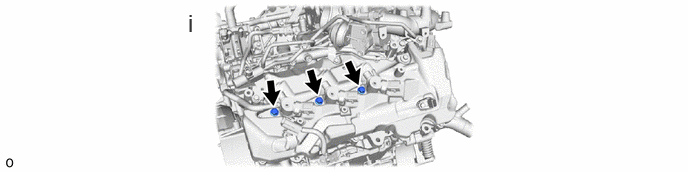
Tighten the 3 bolts.
- Torque:
- 21 N*m (214 kgf*cm, 15 ft.*lbf)
24.INSTALL INJECTION PIPE SUB-ASSEMBLY (for Bank 1)
| *a | Torque Wrench Fulcrum Length | - | - |
Using SST, tighten the union nut on the injector assembly side of the injection pipe sub-assembly.
- SST
-
09268-78010
- Torque:
- Specified tightening torque:
-
55 N*m (561 kgf*cm, 41 ft.*lbf)
- HINT:
-
·
Calculate the torque wrench reading when changing the fulcrum length of the torque wrench.
Click hereGeneral>INTRODUCTION>REPAIR INSTRUCTION>PRECAUTION
·When using SST (fulcrum length of 34.5 mm (1.36 in.)) + torque wrench (fulcrum length of 180 mm (7.09 in.)): 46.2 N*m (471 kgf*cm, 34 ft.*lbf)
Using a 17 mm union nut wrench, tighten the union nut on the common rail assembly side of the injection pipe sub-assembly.
- Torque:
- Specified tightening torque:
-
50 N*m (510 kgf*cm, 37 ft.*lbf)
- HINT:
-
·
Calculate the torque wrench reading when changing the fulcrum length of the torque wrench.
Click hereGeneral>INTRODUCTION>REPAIR INSTRUCTION>PRECAUTION
·When using a union nut wrench (fulcrum length of 30 mm (1.18 in.)) + torque wrench (fulcrum length of 180 mm (7.09 in.)): 42.9 N*m (437 kgf*cm, 32 ft.*lbf)
23760A 25.INSTALL GASKET
23761A 26.INSTALL NO. 1 NOZZLE LEAKAGE PIPE
- Torque:
- 12 N*m (122 kgf*cm, 9 ft.*lbf)
17946 27.INSTALL NO. 2 INTERCOOLER SUPPORT BRACKET
- Torque:
- 21 N*m (214 kgf*cm, 15 ft.*lbf)
17117A 28.INSTALL INTAKE PIPE INSULATOR
- Torque:
- 11.5 N*m (117 kgf*cm, 8 ft.*lbf)
16206B 29.INSTALL NO. 3 WATER BY-PASS PIPE SUB-ASSEMBLY (w/ DPF)
w/ Urea SCR System:
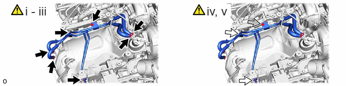
|
|
Bolt A |
|
Bolt B |
Install the No. 18 water by-pass hose and No. 19 water by-pass hose to the exhaust fuel addition injector assembly, and slide the 2 clamps to secure the 2 hoses.
Install the No. 20 water by-pass hose and No. 21 water by-pass hose to the urea injector assembly, and slide the 2 clamps to secure the 2 hoses.
Temporarily install the No. 3 water by-pass pipe sub-assembly to the intercooler support bracket with the 3 bolts.
Tighten the bolt A.
- Torque:
- 10 N*m (102 kgf*cm, 7 ft.*lbf)
Tighten the bolt B.
- Torque:
- 10 N*m (102 kgf*cm, 7 ft.*lbf)
w/o Urea SCR System:
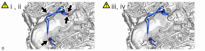
|
|
Bolt A |
|
Bolt B |
Install the No. 18 water by-pass hose and No. 19 water by-pass hose to the exhaust fuel addition injector assembly, and slide the 2 clamps to secure the 2 hoses.
Temporarily install the No. 3 water by-pass pipe sub-assembly to the intercooler support bracket with the 2 bolts.
Tighten the bolt A.
- Torque:
- 10 N*m (102 kgf*cm, 7 ft.*lbf)
Tighten the bolt B.
- Torque:
- 10 N*m (102 kgf*cm, 7 ft.*lbf)
17273A 30.INSTALL TURBO INSULATOR STAY
- Torque:
- 10 N*m (102 kgf*cm, 7 ft.*lbf)
23901H 31.INSTALL FUEL TUBE SUB-ASSEMBLY (w/ DPF)
89463C 32.CONNECT NO. 1 NITROGEN OXIDES SENSOR (w/ Urea SCR System)
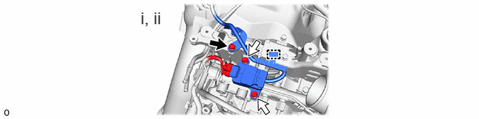
|
|
Bolt A |
|
Bolt B |
Attach the clamp and connect the No. 1 nitrogen oxides sensor with the 3 bolts.
- Torque:
- for bolt A : 8.0 N*m (82 kgf*cm, 6 ft.*lbf)
- for bolt B : 13 N*m (133 kgf*cm, 10 ft.*lbf)
Connect the connector to the No. 1 nitrogen oxides sensor.
162A1A 33.INSTALL TURBO WATER PIPE STAY
- Torque:
- 14 N*m (143 kgf*cm, 10 ft.*lbf)
25860D 34.INSTALL NO. 2 VACUUM SWITCHING VALVE ASSEMBLY
- Torque:
- 10 N*m (102 kgf*cm, 7 ft.*lbf)
1629D 35.CONNECT NO. 17 WATER BY-PASS HOSE (w/ DPF)
1629B 36.CONNECT NO. 15 WATER BY-PASS HOSE (w/ DPF)
51460C 37.INSTALL REAR ENGINE SIDE UNDER COVER ASSEMBLY RH
- Torque:
- 6.0 N*m (61 kgf*cm, 53 in.*lbf)
17940D 38.INSTALL INTERCOOLER ASSEMBLY
39.CONNECT CABLE TO NEGATIVE BATTERY TERMINAL
40.BLEED AIR FROM FUEL SYSTEM
41. INITIALIZATION AFTER RECONNECTING BATTERY TERMINAL
Click hereGeneral>SETUP>WHEN DISCONNECTING OR RECONNECTING BATTERY TERMINAL>WORK PROCEDURE
- HINT:
-
When disconnecting and reconnecting the battery, there is an automatic learning function that completes learning when the respective system is used.
-
Click hereGeneral>SETUP>WHEN DISCONNECTING OR RECONNECTING BATTERY TERMINAL>AUTOMATIC LEARNING CHART
42.INSPECT FOR FUEL LEAK