LIGHTING (EXT) HEADLIGHT ASSEMBLY REASSEMBLY
CAUTION / NOTICE / HINT
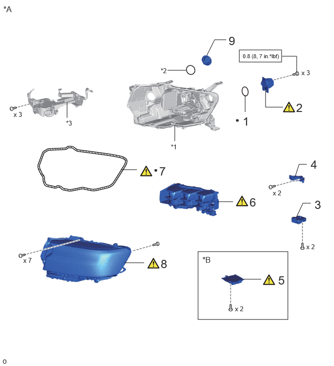
| Procedure | Part Name Code |

|

|

|
|
|---|---|---|---|---|---|
| 1 | GASKET | 81117B | - | - | - |
| 2 | HEADLIGHT LED UNIT ASSEMBLY LH | 81160A | ( ) |
- | - |
| 3 | HEADLIGHT LEVELING MOTOR LH | 85691 | - | - | - |
| 4 | HEADLIGHT BRACKET LH | 81156A | - | - | - |
| 5 | LIGHT CONTROL LED ECU LH | 85967D | () |
- | - |
| 6 | HEADLIGHT UNIT LH | 81171A | () |
- | - |
| 7 | HEADLIGHT LENS GASKET | 81132B | () |
- | - |
| 8 | HEADLIGHT LENS SUB-ASSEMBLY LH | 8110B | () |
- | - |
| 9 | NO. 1 HEADLIGHT COVER | 81144 | - | - | - |
| *A | w/ Headlight ECU | *B | w/ Sequential Turn Light |
| *1 | Headlight Housing LH | *2 | Gasket |
| *3 | BASE B ASSEMBLY | - | - |

|
N*m (kgf*cm, ft.*lbf): Specified torque | - | - |
| ● | Non-reusable part | - | - |
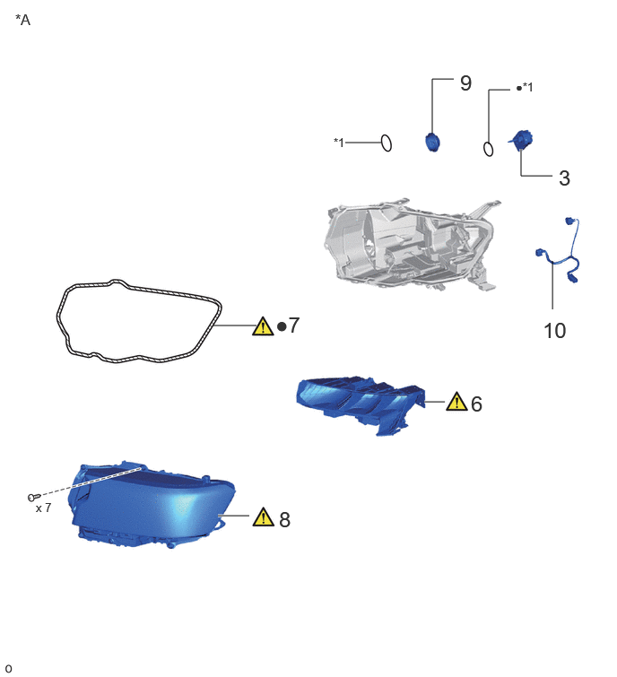
| Procedure | Part Name Code |
|
|
|
|
|---|---|---|---|---|---|
| 3 | HEADLIGHT LEVELING MOTOR LH | 85691 | - | - | - |
| 6 | HEADLIGHT UNIT LH | 81171A | () |
- | - |
| 7 | HEADLIGHT LENS GASKET | 81132B | () |
- | - |
| 8 | HEADLIGHT LENS SUB-ASSEMBLY LH | 8110B | () |
- | - |
| 9 | NO. 1 HEADLIGHT COVER | 81144 | - | - | - |
| 10 | HEADLIGHT CORD LH | 81165 | - | - | - |
| *A | w/o Headlight ECU | - | - |
| *1 | Gasket | - | - |
| ● | Non-reusable part | - | - |
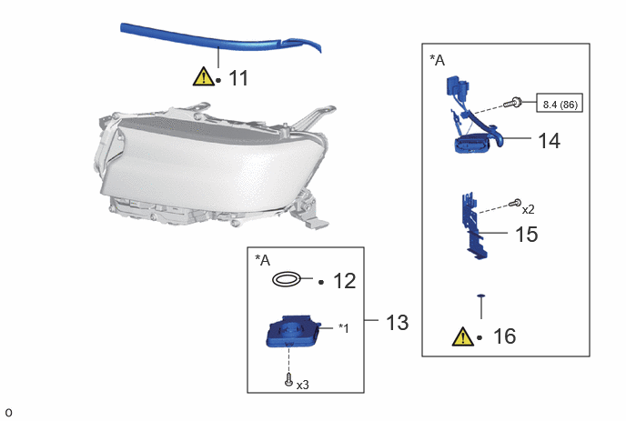
| Procedure | Part Name Code |
|
|
|
|
|---|---|---|---|---|---|
| 11 | NO. 1 HEADLIGHT PROTECTOR LH | 81176 | () |
- | - |
| 12 | HEADLIGHT GASKET | 81134 | - | - | - |
| 13 | HEADLIGHT ECU SUB-ASSEMBLY LH | 81056A | - | - | - |
| 14 | HEADLIGHT CORD LH | 81165 | - | - | - |
| 15 | HEADLIGHT BRACKET LH | 81156A | - | - | - |
| 16 | HEADLIGHT LENS GASKET | 81132B | () |
- | - |
| *A | w/ Headlight ECU | - | - |
| *1 | HEADLIGHT ECU LH | - | - |
| ● | Non-reusable part | - | - |
CAUTION / NOTICE / HINT
- HINT:
-
·
Use the same procedure for the RH and LH sides.
·The procedure listed below is for the LH side.
PROCEDURE

 81117B 1.INSTALL GASKET (w/ Headlight ECU)
81160A 2.INSTALL HEADLIGHT LED UNIT ASSEMBLY LH (w/ Headlight ECU)
- Torque:
- 0.8 N*m (8 kgf*cm, 7 in.*lbf)
85691 3.INSTALL HEADLIGHT LEVELING MOTOR LH
81156A 4.INSTALL HEADLIGHT BRACKET LH
85967D 5.INSTALL LIGHT CONTROL LED ECU LH (w/ Sequential Turn Light)
|
|
() |
81171A 6.INSTALL HEADLIGHT UNIT LH
|
|
|
- SST
-
09890-47010 (09891-04020, 09891-04010, 09891-04030, 09891-04040)
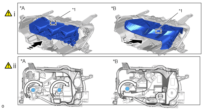
| *A | w/ Headlight ECU | *B | w/o Headlight ECU |
| *1 | Pivot Collar | - | - |

|
Install in this Direction |

|
Turn in this Direction |
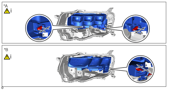
Attach the pivot collar and temporarily install the headlight unit assembly LH to the headlight housing LH as shown in the illustration.
Hold the headlight unit assembly LH with one hand to prevent it from tipping over, alternately tighten the aiming screws for the beam axis horizontal and vertical adjustments in the direction indicated by the arrow shown in the illustration.
| *A | w/ Headlight ECU | *B | w/o Headlight ECU |
Align the dimensions with the recorded values at removal.
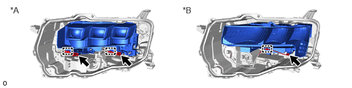
| *A | w/ Headlight ECU | *B | w/o Headlight ECU |
Connect the each connector and attach the wire harness clamp.
81132B 7.INSTALL HEADLIGHT LENS GASKET
|
|
|
- SST
-
09890-47010 (09891-04020, 09891-04010, 09891-04030, 09891-04040)
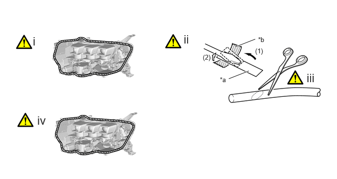
| *a | Peeling Paper | *b | Tape |
Clean the headlight lens gasket installation groove.
Cut the peeling paper and secure with tape to the tip of a screwdriver in the order shown in the illustration.
- NOTICE:
-
Use the peeling paper attached to the new headlight lens gasket.
Using scissors, cut the end of the headlight lens gasket at a 45° angle.
Insert the headlight lens gasket into the groove of the headlight assembly LH so that the joint comes to the bottom.
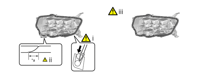
| *a | 10 mm (0.394 in.) +/- 5 mm (0.197 in.) | - | - |
Using a screwdriver with the tip wrapped with peeling paper, push in the headlight lens gasket to the groove bottom of the headlight assembly LH.
- NOTICE:
-
·
Gently set the headlight lens gasket into place without pulling on it.
·If the headlight lens gasket is set while pulled, the gasket will be lifted up at the corner groove.
After completely pushing in the headlight lens gasket, install it so that the edge overlaps itself by 10 mm (0.394 in.) +/- 5 mm (0.197 in.) or more.
Check the installation condition of the headlight lens gasket.
- NOTICE:
-
·
Do not allow the headlight lens gasket to lift up or protrude.
·Do not allow gaps where the headlight lens gasket overlaps.
·Check the corner groove carefully since the gasket can easily become
8110B 8.INSTALL HEADLIGHT LENS SUB-ASSEMBLY LH
|
|
|
- SST
-
09890-47010 (09891-04020, 09891-04010, 09891-04030, 09891-04040)
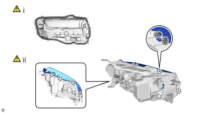

|
Place Hand Here |

|
Cleaning Area |
Be sure to clean the headlight lens gasket contact surface of the headlight lens sub-assembly LH.
Attach the claw and install the headlight lens sub-assembly LH.

| *A | w/ Headlight ECU | - | - |
| *a | "TORX" Screw | - | - |
w/ Headlight ECU:
Install the 7 screws.
Using a T20H "TORX" driver, install the "TORX" screw.
w/o Headlight ECU:
Install the 6 screws.
Using a T20H "TORX" driver, install the "TORX" screw.
81144 9.INSTALL NO. 1 HEADLIGHT COVER
81165 10.INSTALL HEADLIGHT CORD LH (w/o Headlight ECU)
81176 11.INSTALL NO. 1 HEADLIGHT PROTECTOR LH
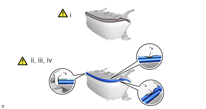
| *a | Mark-off line | - | - |
|
|
Cleaning Area | - | - |
Clean the application area shown in the illustration.
Align with the mark-off line and set the No. 1 headlight protector LH into place.
Align the No. 1 headlight protector LH with the curve and set only the part where the peeling type tape was removed from into place.
Press the set portion of the part with your finger to secure it.
- NOTICE:
-
Do not slide your finger horizontally, as doing so may stretch the part unnecessarily.
81134 12.INSTALL HEADLIGHT GASKET (w/ Headlight ECU)
81056A 13.INSTALL HEADLIGHT ECU SUB-ASSEMBLY LH (w/ Headlight ECU)
81165 14.INSTALL HEADLIGHT CORD LH (w/ Headlight ECU)
81156A 15.INSTALL HEADLIGHT BRACKET LH (w/ Headlight ECU)
- Torque:
- 8.4 N*m (86 kgf*cm, 74 in.*lbf)
81132B 16.INSTALL HEADLIGHT LENS GASKET (w/ Headlight ECU)
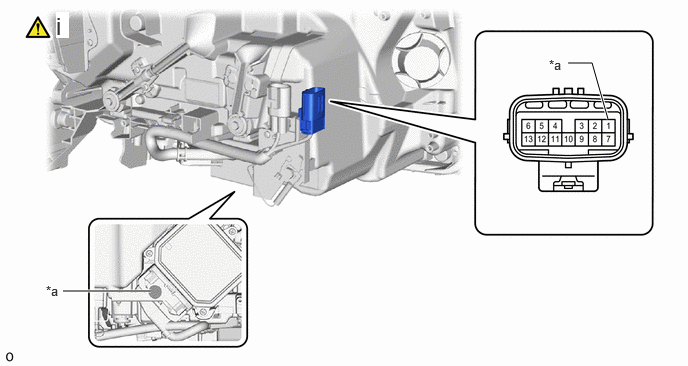
| *a | Measurement Points | - | - |
Measure the resistance of the terminals shown in the figure and confirm that there is continuity.
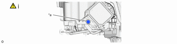
| *a | Mark-off Line | - | - |
Install the headlight plate tape:
1. Clean the installation area surface.
2. Align the mark-off line and install a new headlight plate tape.