1HZ ENGINE MECHANICAL ENGINE ON-VEHICLE INSPECTION
PROCEDURE

 1.ADJUST INJECTION TIMING
Set No. 1 or No. 6 cylinder to TDC/compression.
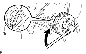
| *a | Pulley Groove |
| *b | Timing Gear Cover Groove |
Turn the crankshaft pulley clockwise, and align its groove with timing gear cover groove.
Install SST and dial indicator.
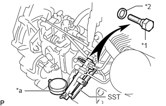
| *1 | Plug Bolt |
| *2 | Gasket |
| *a | Dial Indicator |
Remove the plug bolt and gasket from the distributive head plug of the injection pump.
Install SST and a dial indicator to the plug bolt hole of distributive head plug.
- SST
-
09275-54011
Release ASCD advance (w/ ACSD).
Using a screwdriver, turn the cold starting lever counterclockwise approx. 20°.
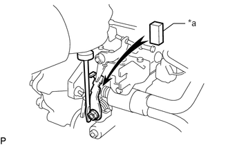
| *a | Metal Plate |
Put a metal plate (thickness of 3.5 to 7.5 mm (0.135 to 0.295 in.)) between the cold starting lever and thermo wax plunger.
Adjust injection timing.
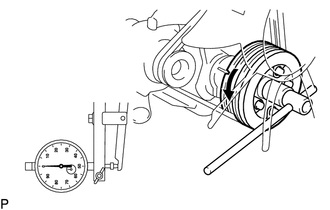
Slowly rotate the crankshaft pulley counterclockwise and set the dial indicator at 0 mm (0 in.) when the dial indicator reaches the minimum value.*1
- NOTICE:
-
Compared with previous 4 cylinder engines, the 0 mm (0 in.) position (crank angle) is reduced, so perform the operation carefully.
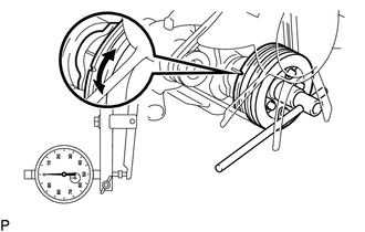
Turn the crankshaft to the left and right and check that the dial indicator shows the minimum value.*2
- NOTICE:
-
Make sure that the minimum value is set at 0 mm (0 in.).
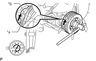
| *a | Pulley Groove |
| *b | Timing Gear Cover Groove |
Slowly rotate the crankshaft pulley clockwise until pulley groove is aligned with the timing gear cover groove.*3
Measure the plunger stroke.
- Standard plunger stroke:
-
1.03 to 1.09 mm (0.0406 to 0.0429 in.)
Repeat steps *1 through *3.
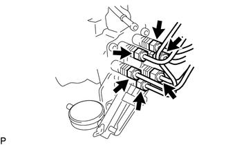
Loosen the following nuts and bolt.
6 union nuts of injection pipes at injection pump side.
Click hereEngine / Hybrid System>1HZ (FUEL)>FUEL INJECTION PUMP>REMOVAL
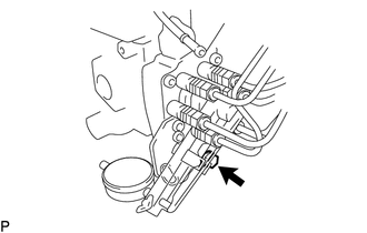
Bolt holding injection pump to injection pump stay.
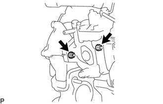
2 nuts holding injection pump to timing gear case sub-assembly.
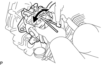
Adjust plunger stroke by slightly tilting the injection pump body.
If the stroke is less than specifications, tilt the injection pump toward the engine.
If the stroke is more than specification, tilt the injection pump away from the engine.
Tighten the following nuts and bolt.
2 nuts holding injection pump to timing gear case sub-assembly.
- Torque:
-
18 N*m (184 kgf*cm, 13 ft.*lbf)
Bolt holding injection pump to injection pump stay.
- Torque:
-
69 N*m (704 kgf*cm, 51 ft.*lbf)
Recheck the plunger stroke.
Remove metal plate (w/ ACSD).
Remove SST and dial indicator.
Remove SST and the dial indicator.
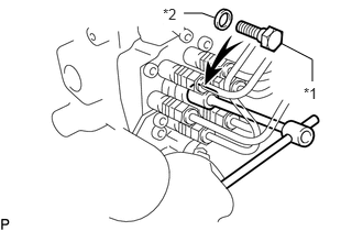
| *1 | Plug Bolt |
| *2 | New Gasket |
Install a new gasket and the plug bolt of the distributive head plug.
- Torque:
- 16.7 N*m (170 kgf*cm, 12 ft.*lbf)
Tighten 6 union nuts of injection pipes at injection pump side.
Click hereEngine / Hybrid System>1HZ (FUEL)>FUEL INJECTION PUMP>INSTALLATION
Start the engine.
Inspect for fuel leaks.
Click hereEngine / Hybrid System>1HZ (FUEL)>FUEL SYSTEM>ON-VEHICLE INSPECTION
2.ADJUST ENGINE IDLE SPEED AND MAXIMUM ENGINE SPEED
Initial conditions.
Engine at reach normal operating temperature.
Air cleaner installed.
All accessories switched off.
All vacuum lines properly connected.
Valve clearance set correctly.
Injection timing set correctly.
Transmission in neutral position.
Connect the tachometer.
Adjust the engine idle speed.
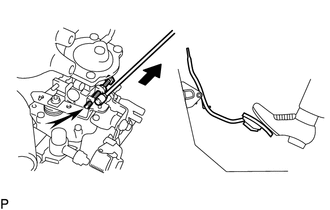
Check that the adjusting lever touches the engine idle speed adjusting screw when the accelerator pedal is released.
If not, adjust the accelerator linkage.
Start the engine.
Check the engine idle speed.
- Standard engine idle speed:
-
600 to 700 rpm
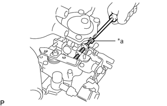
| *a | Engine Idle Speed Adjusting Screw |
Adjust the engine idle speed.
Disconnect the accelerator linkage.
Loosen the lock nut of the engine idle speed adjusting screw.
Adjust the engine idle speed by turning the engine idle speed adjusting screw.
- Standard engine idle speed:
-
650 rpm
Securely tighten the lock nut, and recheck the engine idle speed.
Connect the accelerator linkage.
After adjustment, adjust the accelerator linkage.
Adjust the maximum engine speed.
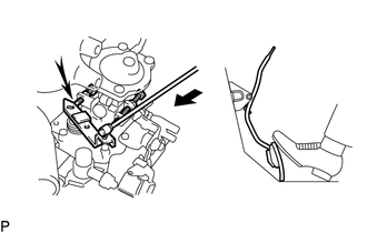
Check that the adjusting lever touches the maximum engine speed adjusting screw when the accelerator pedal is depressed all the way.
If not, adjust the accelerator linkage.
Start the engine.
Depress the accelerator pedal all the way.
Check the maximum engine speed.
- Maximum engine speed:
-
4500 to 4700 rpm
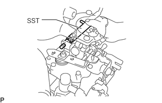
Adjust the maximum engine speed.
- SST
-
09275-54020
Disconnect the accelerator linkage.
Cut out the seal wire of the maximum engine speed adjusting screw.
w/ High Altitude Compensator:
Using SST, loosen the lock nut of maximum engine speed adjusting screw.
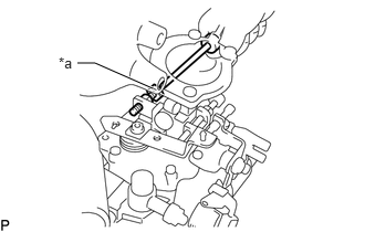
| *a | Maximum Engine Speed Adjusting Screw |
w/o High Altitude Compensator:
Loosen the lock nut of the maximum engine speed adjusting screw.
Adjusting the maximum engine speed by turning the maximum engine speed adjusting screw.
- Maximum engine speed:
-
4600 rpm
- HINT:
-
Adjust is engine idle speed. Then, raise engine speed and recheck the maximum engine speed.
w/ High Altitude Compensator:
Using SST, securely tighten the lock nut.
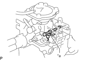
| *a | New Seal Wire |
w/o High Altitude Compensator:
Securely tighten the lock nut.
Recheck the maximum engine speed.
Connect the accelerator linkage.
After adjustment, adjust the accelerator linkage.
Seal the maximum engine speed adjusting screw with a new seal wire.
3.ADJUST AIR CONDITIONER IDLE-UP SETTING SPEED (w/ Air Conditioning System)
Initial conditions.
Engine at reach normal operating temperature.
Air cleaner installed.
All vacuum lines properly connected.
Valve clearance set correctly.
Injection timing set correctly.
Transmission in neutral position.
Engine idle speed set correctly.
Connect the tachometer.
Adjust the air conditioner idle-up setting speed.
Start the engine.
A/C switches on.
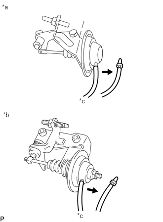
| *a | for Type A |
| *b | for Type B |
| *c | Vacuum |
Disconnect the vacuum hose from the idle-up actuator.
Apply vacuum to idle-up actuator.
Race the engine to 2500 rpm for a few seconds, release the throttle and check the idle-up setting speed.
- Standard air conditioning idle-up setting speed:
-
825 rpm
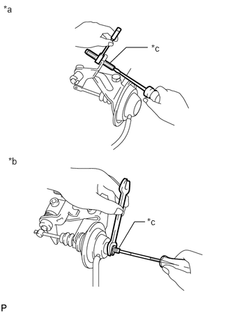
| *a | for Type A |
| *b | for Type B |
| *c | Idle-up Setting Speed Adjusting Screw |
Adjust the air conditioning idle-up setting speed by turning the idle-up setting speed adjusting screw.
Race the engine to 2500 rpm for a few seconds, release the throttle and recheck the air conditioning idle-up setting speed.
Connect the vacuum hose to the idle-up actuator.
4.INSPECT COMPRESSION
- HINT:
-
If there is a lack of power, excessive oil consumption or poor fuel economy is suspected. Measure the compression pressure.
Warm up and stop the engine.
Allow the engine to reach normal operating temperature.
Disconnect the injection pump (fuel cut solenoid) connector.
Remove the glow plugs.
Click hereEngine / Hybrid System>1HZ (STARTING)>GLOW PLUG>REMOVAL
Check the cylinder compression pressure.
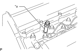
| *a | SST (Attachment) |
Install SST (attachment) to the glow plug hole.
- SST
-
09992-00026 (09992-00160)
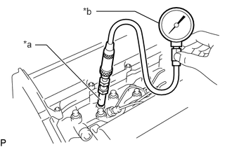
| *a | SST (Attachment) |
| *b | SST (Compression Gauge) |
Connect SST (compression gauge) to SST (attachment).
- SST
-
09992-00026 (09992-00160, 09992-00211)
Fully open the throttle valve, and start the engine.
While cranking the engine, measure the compression pressure.
- NOTICE:
-
This measurement must be done as quickly as possible.
- HINT:
-
Always use a fully charged battery to obtain an engine speed of 250 rpm or more.
Repeat the steps above for each cylinder.
- Standard compression pressure:
-
3628 kPa (37.0 kgf/cm2, 526 psi) or higher
- Minimum pressure:
-
2648 kPa (27.0 kgf/cm2, 384 psi)
- Difference between each cylinder:
-
490 kPa (5.0 kgf/cm2, 71 psi) or less
If the cylinder compression in one or more cylinders is low, pour a small amount of engine oil into the cylinder through the glow plug hole and check the compression pressure for the cylinder with low compression.
- HINT:
-
·
If adding oil helps the compression, the piston rings and/or cylinder bore may be worn or damaged.
·If the pressure stays low, a valve may be stuck or the seating may be improper, or there may be leakage past the gasket.
Remove SST.
Install the glow plugs.
Click hereEngine / Hybrid System>1HZ (STARTING)>GLOW PLUG>INSTALLATION
Connect the injection pump (fuel cut solenoid) connector.