1HZ FUEL FUEL INJECTION PUMP INSTALLATION
PROCEDURE

 1.INSTALL INJECTION PUMP
- NOTICE:
-
Do not position the injection pump (with HAC) at an angle more than 45° from the horizontal direction.
Place the cylinder block insulator in position.
Install a new O-ring to injection pump.
Apply a light coat of engine oil on the O-ring.
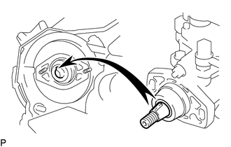
Align the set key on the drive shaft and groove of the injection pump drive gear.
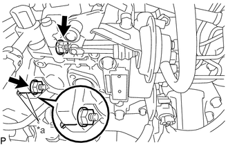
| *a | Matchmarks |
Align the period lines (or matchmarks) of the injection pump and timing belt case.
Install the 2 nuts holding the injection pump to the timing gear case.
- Torque:
- 18 N*m (184 kgf*cm, 13 ft.*lbf)
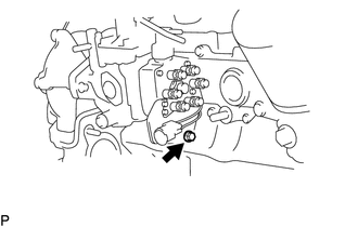
Install the No. 1 injection pump stay with the bolt.
- Torque:
- 69 N*m (704 kgf*cm, 51 ft.*lbf)
- NOTICE:
-
Before tightening to the standard torque, check whether the pump stay is up against the injection pump.
-
If there is a gap, loosen the bolts joining the pump stay to the cylinder block and set the pump stay against the injection pump.
Install a new O-ring to the injection pump drive gear.
Install the injection pump drive gear set nut.
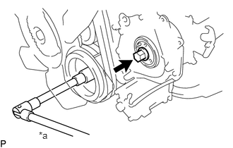
| *a | Hold |
Hold the crankshaft pulley, and tighten the injection pump drive gear set nut.
- Torque:
- 103 N*m (1050 kgf*cm, 76 ft.*lbf)
- NOTICE:
-
Do not turn the crankshaft pulley. The valve heads will hit against the piston top.
2.CHECK INJECTION TIMING
23701 3.INSTALL INJECTION PIPE SUB-ASSEMBLY
4.CONNECT VACUUM HOSE (w/ BACS)
Connect the vacuum hose to the injection pump.
5.CONNECT FUEL HOSE
Connect the 3 fuel hoses to the injection pump, and slide the 3 clamps to secure the hoses.
6.CONNECT INJECTION PUMP CONNECTOR
Connect the injection pump connector.
16264 7.CONNECT NO. 2 WATER BY-PASS HOSE (w/ ACSD)
Connect the No. 2 water by-pass hose to the thermo wax, and slide the clamp to secure the hose.
16261 8.CONNECT WATER BY-PASS HOSE (w/ ACSD)
Connect the water by-pass hose to the thermo wax, and slide the clamp to secure the hose.
9.CONNECT VACUUM HOSE (w/ Air Conditioning System)
Connect the vacuum hose to the idle-up actuator set.
78104 10.INSTALL NO. 2 ACCELERATOR CONNECTING ROD SUB-ASSEMBLY
11.CHECK THROTTLE POSITION SENSOR (w/ BACS)
Disconnect the throttle position sensor connector.
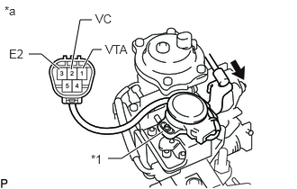
| *1 | Throttle Position Sensor |
| *a | Component without harness connected (Throttle Position Sensor) |
Measure the resistance according to the value(s) in the table below.
- Standard Resistance:
-
Tester Connection Condition Specified Condition 2 (VC) - 3 (E2) - 1.84 to 3.42 kΩ 1 (VTA) - 3 (E2) Accelerator pedal fully released 1.0 to 2.6 kΩ Accelerator pedal fully depressed 0.07 to 0.8 kΩ
- HINT:
-
The resistance between terminals 1 and 3 should change gradually in accordance with the accelerator pedal position.
13528 12.INSTALL CAMSHAFT DRIVE GEAR
13.SET NO. 1 CYLINDER TO BDC/COMPRESSION
13568 14.INSTALL TIMING BELT
13540 15.SET NO. 1 CHAIN TENSIONER ASSEMBLY
13540 16.INSTALL NO. 1 CHAIN TENSIONER ASSEMBLY
17.CHECK VALVE TIMING
11322A 18.INSTALL NO. 1 TIMING BELT COVER
19.ADD COOLANT (w/ ACSD)
20.INSPECT FOR COOLANT LEAK