1HZ FUEL FUEL INJECTION PUMP REMOVAL
PROCEDURE

 1.DRAIN COOLANT (w/ ACSD)
11322A 2.REMOVE NO. 1 TIMING BELT COVER
3.SET NO. 1 CYLINDER TO BDC/COMPRESSION
13568 4.REMOVE TIMING BELT
13528 5.REMOVE CAMSHAFT DRIVE GEAR
78104 6.REMOVE NO. 2 ACCELERATOR CONNECTING ROD SUB-ASSEMBLY
7.DISCONNECT VACUUM HOSE (w/ Air Conditioning System)
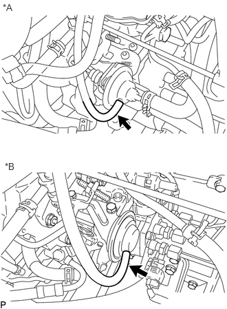
| *A | w/ ACSD |
| *B | w/o ACSD |
Disconnect the vacuum hose from the idle-up actuator set.
16261 8.DISCONNECT WATER BY-PASS HOSE (w/ ACSD)
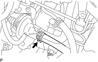
Slide the clamp and disconnect the water by-pass hose from the thermo wax.
16264 9.DISCONNECT NO. 2 WATER BY-PASS HOSE (w/ ACSD)
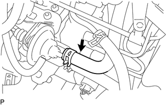
Slide the clamp and disconnect the No. 2 water by-pass hose from the thermo wax.
10.DISCONNECT INJECTION PUMP CONNECTOR
Disconnect the injection pump connector.
11.DISCONNECT FUEL HOSE
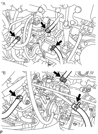
| *A | w/ BACS and HAC |
| *B | w/o BACS and HAC |
Slide the 3 clamps and disconnect the 3 fuel hoses from the injection pump.
12.DISCONNECT VACUUM HOSE (w/ BACS)
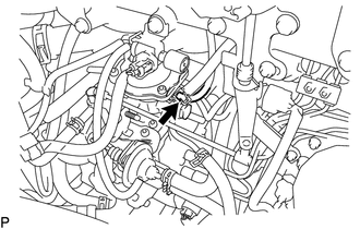
Disconnect the vacuum hose from the injection pump.
23701 13.REMOVE INJECTION PIPE SUB-ASSEMBLY
14.REMOVE INJECTION PUMP
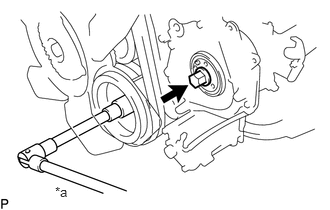
| *a | Hold |
Hold the crankshaft pulley, and remove the injection pump drive gear set nut.
- NOTICE:
-
Do not turn the crankshaft pulley. The valve heads will hit against the piston top.
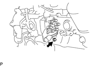
Remove the bolt holding the injection pump to the No. 1 injection pump stay.
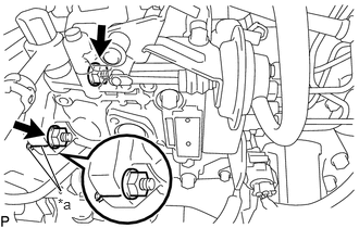
| *a | Matchmarks |
Before removing the injection pump, check if the period lines are aligned.
If not, place new matchmarks for reinstallation.
Remove the 2 nuts holding the injection pump to the timing gear case.
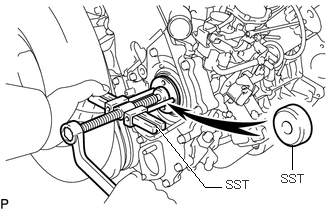
Using SST, remove the injection pump.
- SST
-
09950-50013 (09951-05010, 09952-05010, 09953-05020, 09954-05031, 09957-04010)
- NOTICE:
-
·
Tighten the two bolts more than 8 mm (0.315 in.).
·Set SST so that it is balanced.
·Do not hold or carry the injection pump by the adjusting lever.
Remove the O-ring from the injection pump.