1VD-FTV ENGINE CONTROL ECD SYSTEM P0045 Turbocharger / Supercharger Boost Control Solenoid Circuit / Open
DESCRIPTION
The vacuum regulating valve (VRV) is controlled by the ECM with the duty control. According to the engine state, the VRV controls the vacuum applied to the actuator, which is installed to the turbocharger. If an open or short malfunction occurs in the VRV circuit, this DTC is output.
| DTC No. | Detection Item | DTC Detection Condition | Trouble Area | MIL | Memory |
|---|---|---|---|---|---|
| P0045 | Turbocharger / Supercharger Boost Control Solenoid Circuit / Open | Open or short in vacuum regulating valve (VRV) circuit for 0.5 seconds or more (1 trip detection logic) |
·
Vacuum regulating valve (VRV)
·
Open or short in VRV circuit
·
ECM |
Comes on | DTC stored |
WIRING DIAGRAM
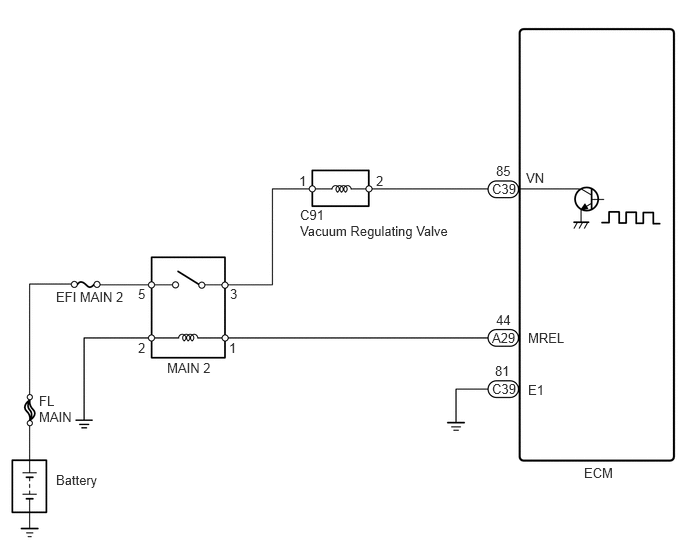
CAUTION / NOTICE / HINT
- NOTICE:
-
·
Inspect the fuses for circuits related to this system before performing the following inspectionprocedure.
·After replacing the ECM, the new ECM needs registration (See page Engine / Hybrid System>1VD-FTV (ENGINE CONTROL)>ECD SYSTEM>REGISTRATION) and initialization(See page Engine / Hybrid System>1VD-FTV (ENGINE CONTROL)>ECD SYSTEM>INITIALIZATION).
- HINT:
-
Read freeze frame data using the GTS. Freeze frame data records the engine condition whenmalfunctions are detected. When troubleshooting, freeze frame data can help determine if the vehicle wasmoving or stationary, if the engine was warmed up or not, and other data from the time the malfunctionoccurred.
PROCEDURE
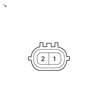
| *a | Component without harness connected (Vacuum Regulating Valve) |
Disconnect the C91 Vacuum Regulating Valve (VRV) connector.
Measure the resistance according to the value(s) in the table below.
- Standard resistance:
-
Tester Connection Condition Specified Condition 1 - 2 20°C (68°F) 11 to 13 Ω
- Result:
-
Proceed to OK NG
OK
NG
Disconnect the C91 VRV connector.
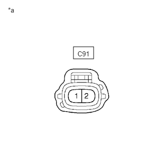
| *a | Front view of wire harness connector (to Vacuum Regulating Valve) |
Measure the voltage according to the value(s) in the table below.
- Standard voltage:
-
Tester Connection Switch Condition Specified Condition C91-1 - Body ground Ignition switch ON 11 to 14 V
- Result:
-
Proceed to OK NG
OK
NG
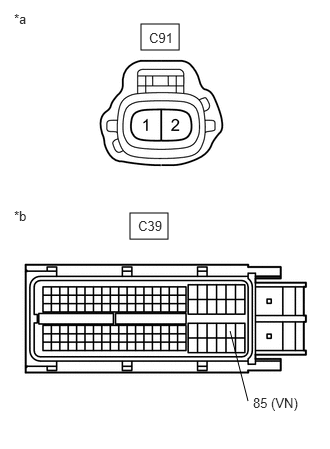
| *a | Front view of wire harness connector (to Vacuum Regulating Valve) |
| *b | Front view of wire harness connector (to ECM) |
Disconnect the C91 VRV connector.
Disconnect the C39 ECM connector.
Measure the resistance according to the value(s) in the table below.
- Standard resistance:
-
Tester Connection Condition Specified Condition C91-2 - C39-85 (VN) Always Below 1 Ω C91-2 or C39-85 (VN) - Body ground Always 10 kΩ or higher
- Result:
-
Proceed to OK NG
OK
NG
Disconnect the C91 VRV connector.
Remove the MAIN 2 relay from the engine room R/B assembly.
Measure the resistance according to the value(s) in the table below.
- Standard resistance:
-
Tester Connection Condition Specified Condition C91-1 - MAIN 2 relay terminal 3 Always Below 1 Ω C91-1 or MAIN 2 relay terminal 3 - Bodyground Always 10 kΩ or higher
- Result:
-
Proceed to OK NG
OK
NG