METER / GAUGE / DISPLAY METER / GAUGE SYSTEM Speed Signal Circuit
DESCRIPTION
The vehicle speed signal consists of pulses sent to the combination meter assembly from the speedometer sensor*1 or brake actuator assembly (skid control ECU)*2.
*1: w/ Speedometer Sensor
*2: w/o Speedometer Sensor
WIRING DIAGRAM
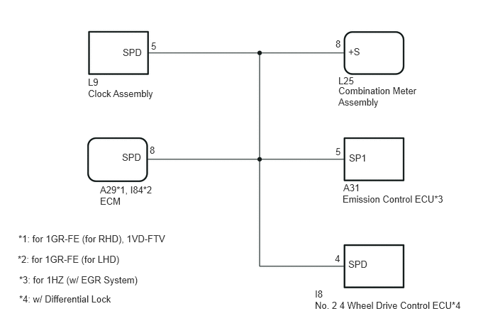
CAUTION / NOTICE / HINT
- NOTICE:
-
If the speedometer operation is not normal, refer to "Speedometer Malfunction".
-
Click hereVehicle Interior>METER / GAUGE / DISPLAY>METER / GAUGE SYSTEM>Speedometer Malfunction
PROCEDURE
*1: for 1GR-FE (for LHD)
*2: for 1GR-FE (for RHD)
*3: for 1VD-FTV
*4: for 1HZ (w/ EGR System)
*5: w/ Differential Lock
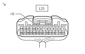
| *a | Rear view of wire harness connector (to Combination Meter Assembly) |
Disconnect the combination meter assembly connector.
Disconnect the I84*1 or A29*2, *3 ECM connector.
Disconnect the A31 emission control ECU connector.*4
Disconnect the I8 No. 2 4 wheel drive control ECU connector.*5
Measure the voltage according to the value(s) in the table below.
- Standard Voltage:
-
Tester Connection Switch Condition Specified Condition L25-8 (+S) - Body ground Ignition switch ON 4.5 to 14 V
- Result:
-
Proceed to OK NG
OK
NG
- NOTICE:
-
For vehicles with a 1HZ, proceed to the next step.
*1: for 1HZ (w/ EGR System)
*2: w/ Differential Lock
| *a | Rear view of wire harness connector (to Combination Meter Assembly) |
Disconnect the combination meter assembly connector.
Disconnect the L9 clock assembly connector.
Disconnect the A31 emission control ECU connector.*1
Disconnect the I8 No. 2 4 wheel drive control ECU connector.*2
Measure the voltage according to the value(s) in the table below.
- Standard Voltage:
-
Tester Connection Switch Condition Specified Condition L25-8 (+S) - Body ground Ignition switch ON 4.5 to 14 V
- Result:
-
Proceed to OK NG
OK
NG
- NOTICE:
-
For vehicles without a 1HZ (w/ EGR system), proceed to the next step.
*1: for 1GR-FE (for LHD)
*2: for 1GR-FE (for RHD)
*3: for 1VD-FTV
*4: w/ Differential Lock
| *a | Rear view of wire harness connector (to Combination Meter Assembly) |
Disconnect the combination meter assembly connector.
Disconnect the L9 clock assembly connector.
Disconnect the I84*1 or A29*2, *3 ECM connector.
Disconnect the I8 No. 2 4 wheel drive control ECU connector.*4
Measure the voltage according to the value(s) in the table below.
- Standard Voltage:
-
Tester Connection Switch Condition Specified Condition L25-8 (+S) - Body ground Ignition switch ON 4.5 to 14 V
- Result:
-
Proceed to OK NG
OK
NG
- NOTICE:
-
For vehicles without a differential lock, proceed to the next step.
*1: for 1GR-FE (for LHD)
*2: for 1GR-FE (for RHD)
*3: for 1VD-FTV
*4: for 1HZ (w/ EGR System)
| *a | Rear view of wire harness connector (to Combination Meter Assembly) |
Disconnect the combination meter assembly connector.
Disconnect the L9 clock assembly connector.
Disconnect the I84*1 or A29*2, *3 ECM connector.
Disconnect the A31 emission control ECU connector.*4
Measure the voltage according to the value(s) in the table below.
- Standard Voltage:
-
Tester Connection Switch Condition Specified Condition L25-8 (+S) - Body ground Ignition switch ON 4.5 to 14 V
- Result:
-
Proceed to OK NG
OK
NG
*1: for 1GR-FE (for LHD)
*2: for 1GR-FE (for RHD)
*3: for 1VD-FTV
*4: for 1HZ (w/ EGR System)
*5: w/ Differential Lock
Disconnect the L25 combination meter assembly connector.
Disconnect the L9 clock assembly connector.
Disconnect the I84*1 or A29*2, *3 ECM connector.
Disconnect the A31 emission control ECU connector.*3
Disconnect the I8 No. 2 4 wheel drive control ECU connector.*5
Measure the resistance according to the value (s) in the table below.
- Standard Resistance:
-
Tester Connection Condition Specified Condition L25-8 (+S) - L9-5 (SPD) Always Below 1 Ω L25-8 (+S) or L9-5 (SPD) - Body ground Always 10 kΩ or higher
- Result:
-
Proceed to OK NG
OK
NG
*1: for 1GR-FE (for LHD)
*2: for 1GR-FE (for RHD)
*3: for 1VD-FTV
*4: for 1HZ (w/ EGR System)
*5: w/ Differential Lock
Disconnect the L25 combination meter assembly connector.
Disconnect the L9 clock assembly connector.
Disconnect the I84*1 or A29*2, *3 ECM connector.
Disconnect the A31 emission control ECU connector.*4
Disconnect the I8 No. 2 4 wheel drive control ECU connector.*5
Measure the resistance according to the value (s) in the table below.
- Standard Resistance:
-
for 1GR-FE (for LHD) Tester Connection Condition Specified Condition L25-8 (+S) - I84-8 (SPD) Always Below 1 Ω L25-8 (+S) or I84-8 (SPD) - Body ground Always 10 kΩ or higher
-
for 1GR-FE (for RHD), 1VD-FTV Tester Connection Condition Specified Condition L25-8 (+S) - A29-8 (SPD) Always Below 1 Ω L25-8 (+S) or A29-8 (SPD) - Body ground Always 10 kΩ or higher
- Result:
-
Result Proceed to OK (for 1GR-FE) A OK (for 1VD-FTV) B NG C
A
B
C
*1: for 1GR-FE (for LHD)
*2: for 1GR-FE (for RHD)
*3: for 1VD-FTV
*4: for 1HZ (w/ EGR System)
*5: w/ Differential Lock
Disconnect the L25 combination meter assembly connector.
Disconnect the L9 clock assembly connector.
Disconnect the I84*1 or A29*2, *3 ECM connector.
Disconnect the A31 emission control ECU connector.*3
Disconnect the I8 No. 2 4 wheel drive control ECU connector.*4
Measure the resistance according to the value (s) in the table below.
- Standard Resistance:
-
Tester Connection Condition Specified Condition L25-8 (+S) - A31-5 (SP1) Always Below 1 Ω L25-8 (+S) or A31-5 (SP1) - Body ground Always 10 kΩ or higher
- Result:
-
Proceed to OK NG
OK
NG
*1: for 1GR-FE (for LHD)
*2: for 1GR-FE (for RHD)
*3: for 1VD-FTV
*4: for 1HZ (w/ EGR System)
*5: w/ Differential Lock
Disconnect the L25 combination meter assembly connector.
Disconnect the L9 clock assembly connector.
Disconnect the I84*1 or A29*2, *3 ECM connector.
Disconnect the A31 emission control ECU connector.*3
Disconnect the I8 No. 2 4 wheel drive control ECU connector.*4
Measure the resistance according to the value (s) in the table below.
- Standard Resistance:
-
Tester Connection Condition Specified Condition L25-8 (+S) - I8-4 (SPD) Always Below 1 Ω L25-8 (+S) or I8-4 (SPD) - Body ground Always 10 kΩ or higher
- Result:
-
Proceed to OK NG
OK
NG