HEATING / AIR CONDITIONING FRONT HEATER UNIT INSTALLATION
CAUTION / NOTICE / HINT
- HINT:
-
·
Use the same procedure for RHD and LHD vehicles.
·The procedure listed below is for LHD vehicles.
·A bolt without a torque specification is shown in the standard bolt chart.
Click hereGeneral>SPECIFICATIONS>STANDARD BOLT>SPECIFIED TORQUE FOR STANDARD BOLTS
PROCEDURE

 87107 1.INSTALL HEATER RADIATOR UNIT SUB-ASSEMBLY
Install the heater radiator unit sub-assembly with the 2 bolts and nut.
- Torque:
- 5.0 N*m (51 kgf*cm, 44 in.*lbf)
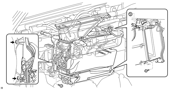
Install the instrument panel wire harness with the 2 screws.
Attach the clamps to install the instrument panel wire harness.
89179A 2.INSTALL AIRBAG SENSOR COVER (w/ Airbag System)
88510 3.INSTALL COOLER UNIT ASSEMBLY
87246A 4.CONNECT HEATER WATER HOSE OUTLET A (w/ Heater)
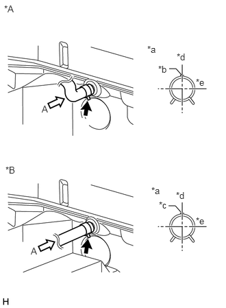
| *A | for 1GR-FE |
| *B | for 1HZ, 1VD-FTV |
| *a | View A |
| *b | Heater Water Outlet Hose Paint Mark (Yellow) |
| *c | Heater Water Outlet Hose Paint Mark (White) |
| *d | Upper Side |
| *e | RH Side |
Connect the heater water outlet hose A with the paint mark (Yellow, White) facing up and attach the clip within the area shown in the illustration.
- NOTICE:
-
Do not apply excessive force to the heater water outlet hose A.
87250 5.CONNECT HOSE AND VALVE ASSEMBLY (w/ Heater)
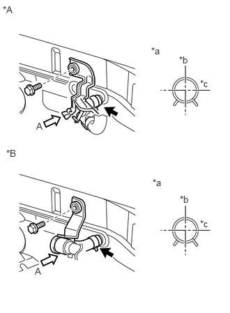
| *A | for 1GR-FE |
| *B | for 1HZ, 1VD-FTV |
| *a | View A |
| *b | Upper Side |
| *c | RH Side |
Connect the hose and valve assembly and attach the clip within the area shown in the illustration.
- NOTICE:
-
Do not apply excessive force to the hose and valve assembly.
Install the bolt.
- Torque:
- 5.0 N*m (51 kgf*cm, 44 in.*lbf)
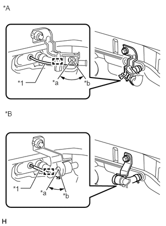
| *A | for 1GR-FE |
| *B | for 1HZ, 1VD-FTV |
| *1 | Water Valve Control Cable Sub-assembly |
| *a | WARM Side |
| *b | COOL Side |
Align the link of the Hose and valve assembly to the COOL side, and then insert the end of the water valve control cable sub-assembly and secure it with clamp.
6.ADD ENGINE COOLANT (w/ Heater)
for 1GR-FE:
Click hereEngine / Hybrid System>1GR-FE (COOLING)>COOLANT>REPLACEMENT
for 1HZ:
Click hereEngine / Hybrid System>1HZ (COOLING)>COOLANT>REPLACEMENT
for 1VD-FTV:
Click hereEngine / Hybrid System>1VD-FTV (COOLING)>COOLANT>REPLACEMENT
7.WARM UP ENGINE (w/ Heater)
8.CHECK FOR ENGINE COOLANT LEAK (w/ Heater)
for 1GR-FE:
Click hereEngine / Hybrid System>1GR-FE (COOLING)>COOLANT>REPLACEMENT
for 1HZ:
Click hereEngine / Hybrid System>1HZ (COOLING)>COOLING SYSTEM>ON-VEHICLE INSPECTION
for 1VD-FTV:
Click hereEngine / Hybrid System>1VD-FTV (COOLING)>COOLING SYSTEM>ON-VEHICLE INSPECTION