HF1A TRANSFER / 4WD / AWD TRANSFER ASSEMBLY REASSEMBLY
PROCEDURE

 36109C 1.INSTALL REAR TRANSFER EXTENSION HOUSING OIL SEAL
36231H 2.INSTALL FRONT TRANSFER OUTPUT SHAFT RADIAL BALL BEARING
36105A 3.INSTALL FRONT TRANSFER EXTENSION HOUSING OIL SEAL
33325B 4.INSTALL FRONT TRANSFER EXTENSION HOUSING DUST DEFLECTOR
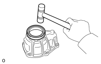
Using a plastic-faced hammer, install the front transfer extension housing dust deflector.
36104B 5.INSTALL TRANSFER OUTPUT SHAFT DUST DEFLECTOR
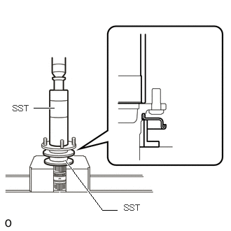
Using SST and a press, install the transfer output shaft dust deflector.
- SST
-
09316-20011
09316-60011 (09316-00011)
- NOTICE:
-
Press in the rear transfer output shaft dust deflector until it fits to the edge.
36239 6.INSTALL TRANSFER DRIVE CLUTCH HUB
36235 7.INSTALL TRANSFER HIGH AND LOW CLUTCH SLEEVE
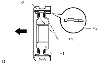
| *1 | Transfer Clutch Hub |
| *2 | No. 2 Synchromesh Shifting Key |
| *3 | Transfer High and Low Clutch Sleeve |
| *4 | Transfer Synchromesh Shifting Key Spring |

|
Front of Vehicle |
Insert the transfer clutch hub and 3 No. 2 synchromesh shifting keys into the transfer high and low clutch sleeve.
Install the 2 transfer synchromesh shifting key springs under the 3 No. 2 synchromesh shifting keys.
- NOTICE:
-
Install the 2 transfer synchromesh shifting key springs positioned so that their end gaps are not in line.
36231E 8.INSTALL FRONT TRANSFER OUTPUT SHAFT NEEDLE ROLLER BEARING
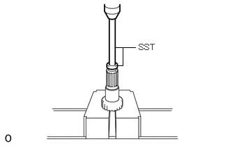
Using SST and a press, press in a new front transfer output shaft needle roller bearing.
- SST
-
09950-60010 (09951-00250)
09950-70010 (09951-07200)
36237 9.INSTALL TRANSFER CLUTCH HUB
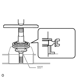
Using SST and a press, install the transfer clutch hub.
- SST
-
09316-20011
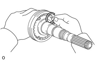
Select a snap ring that will allow minimum axial play and install it on the shaft.
- Standard Thickness:
-
Mark Thickness A 2.60 mm (0.1024 in.) B 2.65 mm (0.1043 in.) C 2.70 mm (0.1063 in.) D 2.75 mm (0.1083 in.) E 2.80 mm (0.1102 in.) F 2.85 mm (0.1122 in.) G 2.90 mm (0.1142 in.)
36242 10.INSTALL TRANSFER LOW GEAR
Apply transfer oil to the transfer output shaft front needle roller bearing.
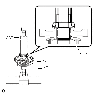
| *1 | Transfer Output Shaft Front Needle Roller Bearing |
| *2 | Transfer Output Shaft Taper Roller Bearing (Inner Race) |
| *3 | Transfer Low Gear |
Using SST and a press, install the transfer low gear and a new transfer output shaft taper roller bearing (inner race) to the output shaft assembly.
- SST
-
09316-60011 (09316-00011)
36203 11.INSTALL TRANSFER HIGH SPEED OUTPUT GEAR SUB-ASSEMBLY
Apply transfer oil to the front transfer output shaft needle roller bearing.
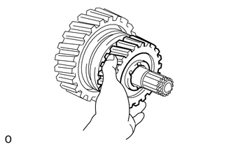
Install the 2 pieces of the front transfer output shaft needle roller bearing and No. 1 transfer output shaft spacer to the transfer high speed output gear sub-assembly.
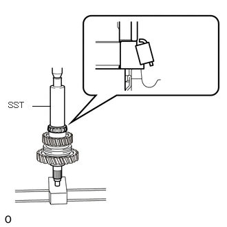
Using SST and a press, install the transfer high speed output gear sub-assembly and a new transfer output shaft taper roller bearing (inner race) to the output shaft assembly.
- SST
-
09316-60011 (09316-00011)
36245 12.INSTALL TRANSFER FRONT DRIVE GEAR PIECE
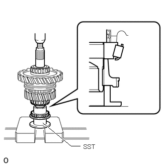
Using SST and a press, install the transfer front drive gear piece.
- SST
-
09316-60011 (09316-00031)
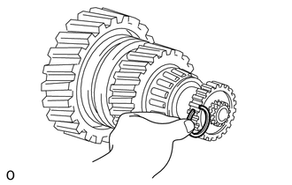
Select a new snap ring that will allow minimum axial play and install it on the shaft.
- Standard Thickness:
-
Mark Thickness A 2.0 mm (0.0787 in.) B 2.1 mm (0.0827 in.) C 2.2 mm (0.0866 in.) D 2.3 mm (0.0906 in.) E 2.4 mm (0.0945 in.)
36203 13.INSPECT TRANSFER HIGH SPEED OUTPUT GEAR THRUST CLEARANCE
36242 14.INSPECT TRANSFER LOW GEAR THRUST CLEARANCE
36203 15.INSPECT TRANSFER HIGH SPEED OUTPUT GEAR RADIAL CLEARANCE
36242 16.INSPECT TRANSFER LOW GEAR RADIAL CLEARANCE
36221G 17.INSTALL TRANSFER ILDER GEAR BEARING (for Front Side)
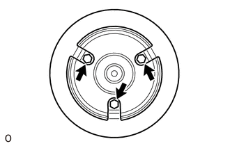
Install the transfer idler gear transfer oil receiver with the 3 bolts.
- Torque:
- 7.84 N*m (80 kgf*cm, 69 in.*lbf)
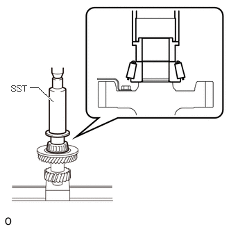
Using SST and a press, install a new transfer idler gear bearing (inner race) to the transfer idler gear.
- SST
-
09316-60011 (09316-00011, 09316-00071)
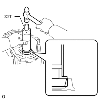
Using SST and a hammer, install a new transfer idler gear bearing (outer race) to the front transfer case.
- SST
-
09316-60011 (09316-00011, 09316-00041)
36221H 18.INSTALL TRANSFER ILDER GEAR BEARING (for Rear Side)
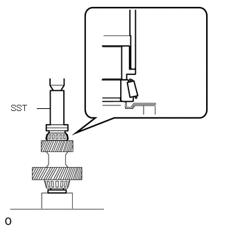
Using SST and a press, install a new transfer idler gear bearing (inner race) to the transfer idler gear.
- SST
-
09316-60011 (09316-00011, 09316-00051)
Install a new transfer idler gear bearing (outer race) to the rear transfer case.
36212F 19.INSTALL FRONT TRANSFER INPUT SHAFT RADIAL BALL BEARING
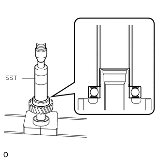
Using SST and a press, install a new front transfer input shaft radial ball bearing.
- SST
-
09316-60011 (09316-00011)
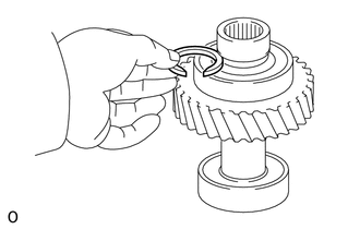
Select a new snap ring that will allow minimum axial play and install it on the shaft.
- Standard Thickness:
-
Mark Thickness A 2.90 mm (0.1142 in.) B 2.95 mm (0.1161 in.) C 3.00 mm (0.1181 in.) D 3.05 mm (0.1201 in.) E 3.10 mm (0.1220 in.) F 3.15 mm (0.1240 in.)
36212A 20.INSTALL TRANSFER INPUT GEAR RADIAL BALL BEARING
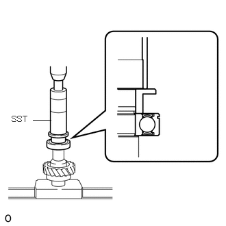
Using SST and a press, install a new transfer input gear radial ball bearing.
- SST
-
09316-60011 (09316-00011, 09316-00031)
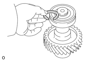
Select a new snap ring that will allow minimum axial play and install it on the shaft.
- Standard Thickness:
-
Mark Thickness A 2.0 mm (0.0787 in.) B 2.1 mm (0.0827 in.) C 2.2 mm (0.0866 in.) D 2.3 mm (0.0906 in.) E 2.4 mm (0.0945 in.)
36231C 21.INSTALL TRANSFER OUTPUT SHAFT TAPER ROLLER BEARING
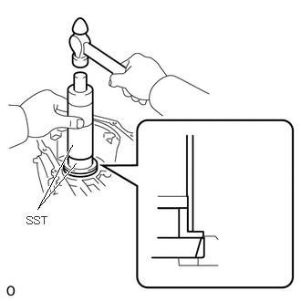
for Front Transfer Case Side:
Using SST and a hammer, install a new transfer output shaft taper roller bearing (outer race) to the front transfer case.
- SST
-
09316-20011
09316-60011 (09316-00011, 09316-00031)
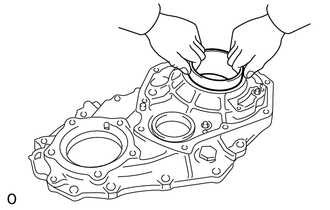
for Rear Transfer Case Side:
Install a new transfer output shaft taper roller bearing (outer race) to the rear transfer case.
36111B 22.INSTALL TRANSFER CASE OIL SEAL
Apply MP grease to the lip of 2 new transfer case oil seals.
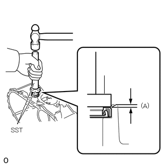
for Transfer Shift Inner Lever Shaft Side:
Using SST and a hammer, install the transfer case oil seal.
- SST
-
09950-60010 (09951-00250)
09950-70010 (09951-07100)
- Drive in depth (A):
-
0 to 0.5 mm (0 to 0.0196 in.)
- NOTICE:
-
·
Tap the transfer case oil seal uniformly so that the transfer case oil seal is straight.
·Make sure the outside edge of the seal is positioned past the chamfered part.
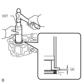
for Input Shaft Side:
Using SST and a hammer, install the transfer case oil seal.
- SST
-
09316-60011 (09316-00011, 09316-00031)
- Drive in depth (A):
-
0 to 0.5 mm (0 to 0.0196 in.)
- NOTICE:
-
·
Tap the transfer case oil seal uniformly so that the transfer case oil seal is straight.
·Make sure the outside edge of the seal is positioned past the chamfered part.
36362A 23.INSTALL TRANSFER SHIFT OUTER LEVER
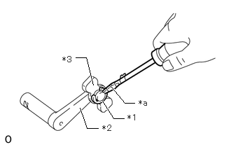
| *1 | E-Ring |
| *2 | Transfer Shift Inner Lever Shaft |
| *3 | Transfer Shift Lever Inner |
| *a | Protective Tape |
Install the transfer shift lever inner to the transfer shift inner lever shaft.
Using a screwdriver, install the E-ring to the transfer shift inner lever shaft.
- HINT:
-
Tape the screwdriver tip before use.
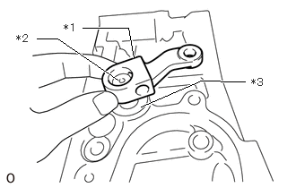
| *1 | Transfer Shift Outer Lever |
| *2 | Transfer Shift Inner Lever Shaft |
| *3 | Washer |
Install the transfer shift inner lever shaft, washer and transfer shift outer lever to the front transfer case.
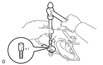
| *1 | Lever Lock Pin |
Using a pin punch and hammer, tap in the lever lock pin.
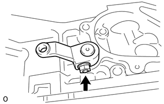
Install the washer and nut.
- Torque:
- 11.76 N*m (120 kgf*cm, 9 ft.*lbf)
36312F 24.INSTALL NO. 2 TRANSFER GEAR SHIFT FORK
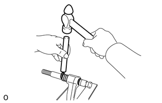
Install the No. 2 transfer gear shift fork and shift detent ball compression spring to the transfer front drive shift fork shaft.
Using a brass bar and hammer, tap in the 2 transfer gear shift fork shaft snap rings.
36236 25.INSTALL FRONT DRIVE CLUTCH SLEEVE
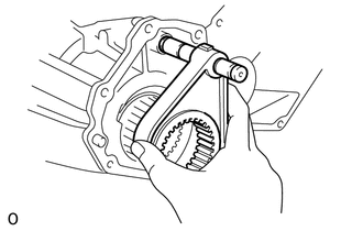
Install the front drive clutch sleeve with the No. 2 transfer gear shift fork and transfer front drive shift fork shaft.
36311F 26.INSTALL NO. 1 TRANSFER GEAR SHIFT FORK
Install the No. 1 transfer gear shift fork to the transfer high and low shift fork shaft.
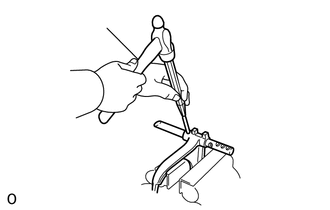
Using a pin punch and hammer, tap in the transfer shift fork slotted spring pin.
27.INSTALL OUTPUT SHAFT ASSEMBLY
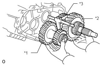
| *1 | Idler Gear Assembly |
| *2 | Output Shaft Assembly |
| *3 | No. 1 Transfer Gear Shift Fork and Transfer High and Low Shift Fork Shaft |
Install the idler gear assembly and output shaft assembly together with the No. 1 transfer gear shift fork and transfer high and low shift fork shaft.
28.INSTALL INPUT SHAFT ASSEMBLY
Using a plastic-faced hammer, tap in the input shaft assembly.
33124E 29.INSTALL TRANSFER OIL RECEIVER PIPE
for Front Transfer Extension Housing Side:
Click hereDrivetrain>HF1A (TRANSFER / 4WD / AWD)>TRANSFER CASE FRONT OIL SEAL>REPLACEMENT
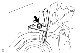
for Front Transfer Case Side:
Clean and degrease the bolt and the installation hole.
Apply adhesive to 2 or 3 threads on the ends of the bolt.
- Adhesive:
-
Toyota Genuine Adhesive 1344, Three Bond 1344 or equivalent
Install the transfer oil receiver pipe with the bolt.
- Torque:
- 11.76 N*m (120 kgf*cm, 9 ft.*lbf)
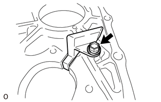
for Rear Transfer Case Side:
Clean and degrease the bolt and the installation hole.
Apply adhesive to 2 or 3 threads on the ends of the bolt.
- Adhesive:
-
Toyota Genuine Adhesive 1344, Three Bond 1344 or equivalent
Install the transfer oil receiver pipe with the bolt.
- Torque:
- 18.13 N*m (185 kgf*cm, 13 ft.*lbf)
33124B 30.INSTALL REAR TRANSFER CASE OIL RECEIVER PIPE
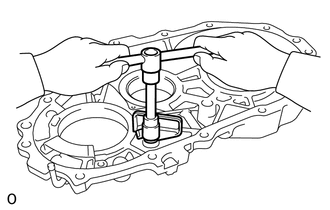
Install the rear transfer case oil receiver pipe with the bolt.
- Torque:
- 11.76 N*m (120 kgf*cm, 9 ft.*lbf)
36112 31.INSTALL REAR TRANSFER CASE
Using a scraper, clean the seal packing from the rear transfer case and front transfer case and remove any oil using a cleaning solvent.
- NOTICE:
-
Do not scratch the installation area.
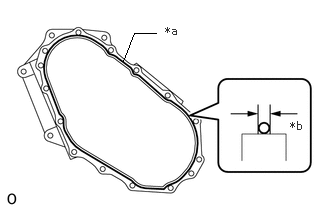
| *a | Seal Packing |
| *b | Seal Width 1.2 mm (0.0472 in.) |
Apply seal packing to the rear transfer case as shown in the illustration.
- Seal packing:
-
Toyota Genuine Seal Packing 1281, Three Bond 1281 or equivalent
- NOTICE:
-
Install the rear transfer case to the case within 10 minutes of application.
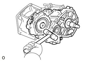
Using a plastic-faced hammer, tap the rear transfer case to install it.
Clean and degrease the bolt and the installation hole.
Apply adhesive to 2 or 3 threads on the ends of the bolt.
- Adhesive:
-
Toyota Genuine Adhesive 1344, Three Bond 1344 or equivalent
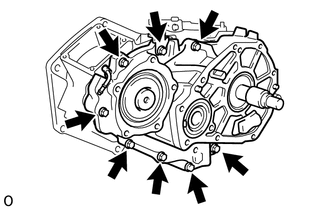
Install the 8 bolts with the bracket.
- Torque:
- 37.24 N*m (380 kgf*cm, 27 ft.*lbf)
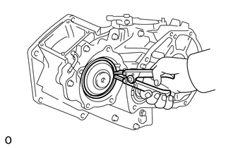
Using snap ring pliers, install the transfer input gear shaft snap ring.
36122 32.INSTALL NO. 2 TRANSFER CASE COVER
Using a scraper, clean the seal packing from the No. 2 transfer case cover and rear transfer case and remove any oil using a cleaning solvent.
- NOTICE:
-
Do not scratch the installation area.
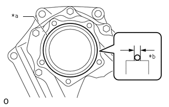
| *a | Seal Packing |
| *b | Seal Width 1.2 mm (0.0472 in.) |
Apply seal packing to the rear transfer case as shown in the illustration.
- Seal packing:
-
Toyota Genuine Seal Packing 1281, Three Bond 1281 or equivalent
- NOTICE:
-
Install the No. 2 transfer case cover to the case within 10 minutes of application.
Clean and degrease the bolt and the installation hole.
Apply adhesive to 2 or 3 threads on the ends of the bolt.
- Adhesive:
-
Toyota Genuine Adhesive 1344, Three Bond 1344 or equivalent
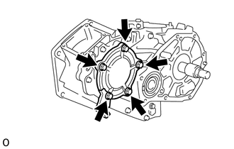
Install the No. 2 transfer case cover with the 5 bolts and bracket.
- Torque:
- 37.24 N*m (380 kgf*cm, 27 ft.*lbf)
36221D 33.INSTALL TRANSFER IDLER GEAR PLATE WASHER
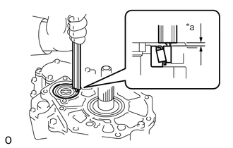
| *a | Dimension A |
Using a vernier caliper with depth gauge, measure dimension A.
- HINT:
-
Lightly hold down the bearing outer race in the thrust direction to eliminate any looseness before making the measurement.
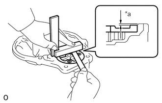
| *a | Dimension B |
Using a feeler gauge and precision straightedge, measure the clearance of dimension B.
Calculate the required thickness of the plate washer.
- Thickness:
-
Dimension A + Dimension B + Dimension C
- Dimension C:
-
0.02 to 0.07 mm (0.00079 to 0.00276 in.)
From the following table, select a plate washer with a thickness fitting within the range of the calculation in (c).
- Standard Thickness:
-
Mark Thickness Mark Thickness 2 0.3 mm (0.0118 in.) 7 3.0 mm (0.118 in.) 3 0.45 mm (0.0177 in.) 8 3.2 mm (0.1260 in.) 13 0.55 mm (0.0217 in.) 9 3.4 mm (0.1339 in.) 4 2.4 mm (0.0945 in.) 10 3.6 mm (0.1417 in.) 5 2.6 mm (0.1024 in.) 11 3.8 mm (0.1496 in.) 6 2.8 mm (0.1102 in.) 12 4.0 mm (0.1575 in.)
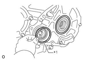
| *1 | Transfer Idler Gear Plate Washer |
Install the transfer idler gear plate washer.
36231K 34.INSTALL TRANSFER OUTPUT REAR CASE PLATE WASHER
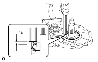
| *a | Dimension D |
Using a vernier caliper with depth gauge, measure dimension D.
- HINT:
-
Lightly hold down the bearing outer race in the thrust direction to eliminate any looseness before making the measurement.
Calculate the required thickness of the plate washer.
- Thickness:
-
Dimension D + Dimension E
- Dimension E:
-
0.04 to 0.09 mm (0.00157 to 0.00354 in.)
From the following table, select a plate washer with a thickness fitting within the range of the calculation in (a).
- Standard Thickness:
-
Mark Thickness Mark Thickness 2 0.3 mm (0.0118 in.) 7 1.6 mm (0.0630 in.) 3 0.45 mm (0.0177 in.) 8 1.8 mm (0.0709 in.) 13 0.55 mm (0.0217 in.) 9 2.0 mm (0.0787 in.) 4 1.0 mm (0.0394 in.) 10 2.2 mm (0.0866 in.) 5 1.2 mm (0.0472 in.) 11 2.4 mm (0.0945 in.) 6 1.4 mm (0.0551 in.) 12 2.6 mm (0.1024 in.)
Install the transfer output rear case plate washer.
36255 35.INSTALL NO. 1 TRANSFER OUTPUT SHAFT SPACER
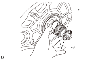
| *1 | No. 1 Transfer Output Shaft Spacer |
| *2 | Transfer Output Rear Shaft Plate Washers |
Install the No. 1 transfer output shaft spacer and 2 transfer output rear shaft plate washers.
36109B 36.INSTALL REAR TRANSFER EXTENSION HOUSING SUB-ASSEMBLY
Using a scraper, clean the seal packing from the rear transfer extension housing sub-assembly and rear transfer case and remove any oil using a cleaning solvent.
- NOTICE:
-
Do not scratch the installation area.
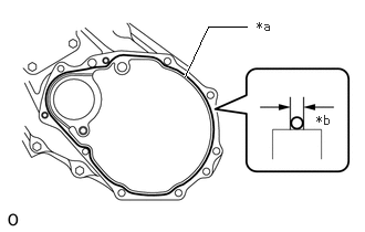
| *a | Seal Packing |
| *b | Seal Width 1.2 mm (0.0472 in.) |
Apply seal packing to the rear transfer extension housing sub-assembly as shown in the illustration.
- Seal packing:
-
Toyota Genuine Seal Packing 1281, Three Bond 1281 or equivalent
- NOTICE:
-
Install the rear transfer extension housing sub-assembly to the case within 10 minutes of application.
Clean and degrease the bolt and the installation hole.
Apply adhesive to 2 or 3 threads on the ends of the bolt.
- Adhesive:
-
Toyota Genuine Adhesive 1344, Three Bond 1344 or equivalent
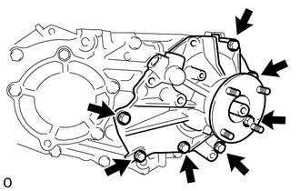
w/ ABS:
Install the rear transfer extension housing sub-assembly with the 7 bolts.
- Torque:
- 37.24 N*m (380 kgf*cm, 27 ft.*lbf)
w/o ABS:
Install the rear transfer extension housing sub-assembly with the 9 bolts.
- Torque:
- 37.24 N*m (380 kgf*cm, 27 ft.*lbf)
36111C 37.INSTALL TRANSFER CASE PLUG
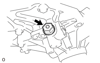
Install the transfer case plug and a new gasket to the rear transfer extension housing sub-assembly.
- Torque:
- 37.24 N*m (380 kgf*cm, 27 ft.*lbf)
36105 38.INSTALL FRONT TRANSFER EXTENSION HOUSING SUB-ASSEMBLY
33309A 39.INSTALL DUST DEFLECTOR
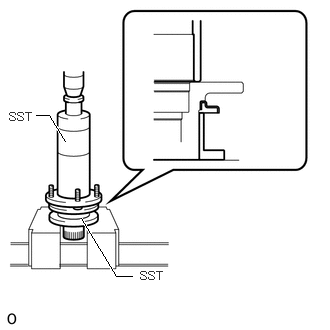
Using SST and a press, install a new dust deflector.
- SST
-
09316-20011
09316-60011 (09316-00011)
- NOTICE:
-
Press in the dust deflector until it fits to the edge.
33481P 40.INSTALL TRANSFER SPEEDOMETER DRIVE GEAR
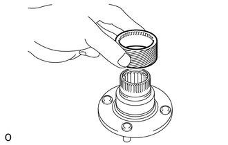
Install the transfer speedometer drive gear.
33309 41.INSTALL TRANSFER OUTPUT SHAFT COMPANION FLANGE SUB-ASSEMBLY
36275 42.INSTALL SHIFT DETENT BALL SPRING PLUG
for Front Transfer Case Side:
Clean and degrease the shift detent ball spring plug and the installation hole.
Apply adhesive to 2 or 3 threads on the ends of the shift detent ball spring plug.
- Adhesive:
-
Toyota Genuine Adhesive 1344, Three Bond 1344 or equivalent
Using a T40 "TORX" socket wrench, install the 2 shift detent ball spring plugs.
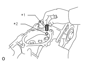
| *1 | Shift Detent Ball Compression Spring |
| *2 | Shift Detent Ball |
Install the shift detent ball and shift detent ball compression spring.
Apply adhesive to 2 or 3 threads of the shift detent ball spring plug.
- Adhesive:
-
Toyota Genuine Adhesive 1344, Three Bond 1344 or equivalent
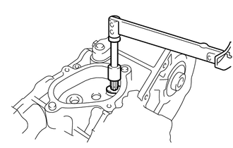
Using a T40 "TORX" socket wrench, install the shift detent ball spring plug.
- Torque:
- 18.62 N*m (190 kgf*cm, 14 ft.*lbf)
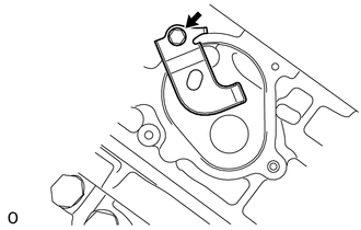
Install the bracket with the bolt.
- Torque:
- 11.76 N*m (120 kgf*cm, 9 ft.*lbf)
for Front Transfer Extension Housing Side:
Click hereDrivetrain>HF1A (TRANSFER / 4WD / AWD)>TRANSFER CASE FRONT OIL SEAL>REPLACEMENT
84222 43.INSTALL NO. 1 TRANSFER INDICATOR SWITCH (L4 POSITION) (w/ ABS)
36336 44.INSTALL TRANSFER HEAT INSULATOR (w/ ABS)
84222 45.INSTALL NO. 1 TRANSFER INDICATOR SWITCH (4WD POSITION)
46.INSTALL SPEEDOMETER DRIVEN GEAR SUB-ASSEMBLY (w/o ABS)
Install the speedometer driven gear sub-assembly with the bolt.
- Torque:
- 16 N*m (163 kgf*cm, 12 ft.*lbf)
33403D 47.INSTALL SPEEDOMETER DRIVEN HOLE COVER SUB-ASSEMBLY (w/ ABS)
Coat a new O-ring with transfer oil and install it to the speedometer driven hole cover sub-assembly.
Install the speedometer driven hole cover sub-assembly with the bolt.
- Torque:
- 16 N*m (163 kgf*cm, 12 ft.*lbf)
36112B 48.INSTALL REAR NO. 1 TRANSFER CASE HOSE
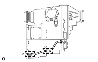
Install the rear No. 1 transfer case hose.
Connect the rear No. 1 transfer case hose to the 2 clamps.
49.ADD TRANSFER OIL