METER / GAUGE / DISPLAY METER / GAUGE SYSTEM Fuel Receiver Gauge Malfunction
DESCRIPTION
The fuel sender gauge assembly has a variable resistance mechanism. The resistance decreases when the fuel amount increases, and the resistance increases when the fuel amount decreases. The fuel receiver gauge float position changes based on the resistance of the fuel sender gauge assembly.
WIRING DIAGRAM
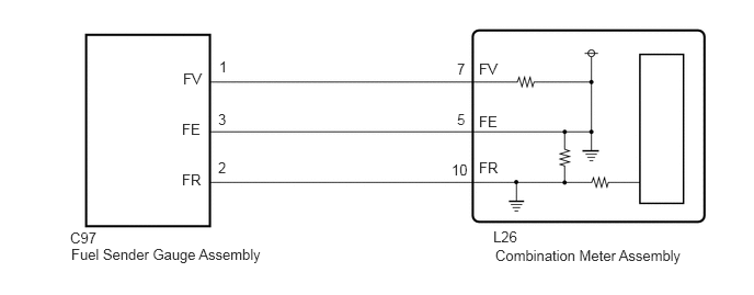
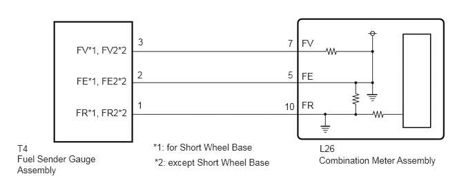
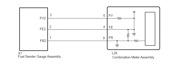
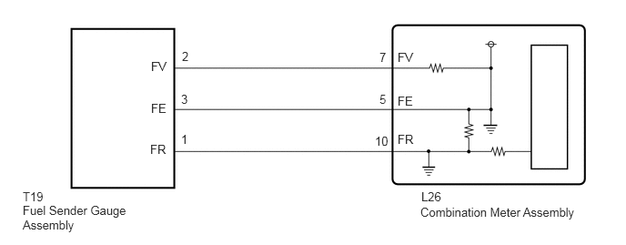
CAUTION / NOTICE / HINT
- CAUTION:
-
Be careful of flames.
PROCEDURE
Remove the fuel sender gauge assembly.
for 1GR-FE, 90 L Tank Carried in Middle: Click hereEngine / Hybrid System>1GR-FE (FUEL)>FUEL SENDER GAUGE ASSEMBLY (for 90 L Tank Carried in Middle)>REMOVAL
for 1GR-FE, 90 L Tank Carried in Rear: Click hereEngine / Hybrid System>1GR-FE (FUEL)>FUEL SENDER GAUGE ASSEMBLY (for 90 L Tank Carried in Rear)>REMOVAL
for 1GR-FE, 130 L Tank: Click hereEngine / Hybrid System>1GR-FE (FUEL)>FUEL SENDER GAUGE ASSEMBLY (for 130 L Tank)>REMOVAL
for 1HZ, 90 L Tank Carried in Middle: Click hereEngine / Hybrid System>1HZ (FUEL)>FUEL SENDER GAUGE ASSEMBLY(for 90 L Tank Carried in Middle)>REMOVAL
for 1HZ, 90 L Tank Carried in Rear: Click hereEngine / Hybrid System>1HZ (FUEL)>FUEL SENDER GAUGE ASSEMBLY(for 90 L Tank Carried in Rear)>REMOVAL
for 1HZ, 130 L Tank: Click hereEngine / Hybrid System>1HZ (FUEL)>FUEL SENDER GAUGE ASSEMBLY(for 130 L Tank)>REMOVAL
for 1VD-FTV, 90 L Tank Carried in Middle: Click hereEngine / Hybrid System>1VD-FTV (FUEL)>FUEL SENDER GAUGE ASSEMBLY(for 90 L Tank Carried in Middle)>REMOVAL
for 1VD-FTV, 130 L Tank: Click hereEngine / Hybrid System>1VD-FTV (FUEL)>FUEL SENDER GAUGE ASSEMBLY(for 130 L Tank)>REMOVAL
Inspect the fuel sender gauge assembly.
for 1GR-FE, 90 L Tank Carried in Middle: Click hereEngine / Hybrid System>1GR-FE (FUEL)>FUEL SENDER GAUGE ASSEMBLY (for 90 L Tank Carried in Middle)>INSPECTION
for 1GE-FE, 90 L Tank Carried in Rear: Click hereEngine / Hybrid System>1GR-FE (FUEL)>FUEL SENDER GAUGE ASSEMBLY (for 90 L Tank Carried in Rear)>INSPECTION
for 1GR-FE, 130 L Tank: Click hereEngine / Hybrid System>1GR-FE (FUEL)>FUEL SENDER GAUGE ASSEMBLY (for 130 L Tank)>INSPECTION
for 1HZ, 90 L Tank Carried in Middle: Click hereEngine / Hybrid System>1HZ (FUEL)>FUEL SENDER GAUGE ASSEMBLY(for 90 L Tank Carried in Middle)>INSPECTION
for 1HZ, 90 L Tank Carried in Rear: Click hereEngine / Hybrid System>1HZ (FUEL)>FUEL SENDER GAUGE ASSEMBLY(for 90 L Tank Carried in Rear)>INSPECTION
for 1HZ, 130 L Tank: Click hereEngine / Hybrid System>1HZ (FUEL)>FUEL SENDER GAUGE ASSEMBLY(for 130 L Tank)>INSPECTION
for 1VD-FTV, 90 L Tank Carried in Middle: Click hereEngine / Hybrid System>1VD-FTV (FUEL)>FUEL SENDER GAUGE ASSEMBLY(for 90 L Tank Carried in Middle)>INSPECTION
for 1VD-FTV, 130 L Tank: Click hereEngine / Hybrid System>1VD-FTV (FUEL)>FUEL SENDER GAUGE ASSEMBLY(for 130 L Tank)>INSPECTION
- Result:
-
Result Proceed to OK (for Double Tank Type) A OK (for Single Tank Type) B NG C
A
B
C
for 1GR-FE, 90 L Tank Carried in Middle: Click hereEngine / Hybrid System>1GR-FE (FUEL)>FUEL SENDER GAUGE ASSEMBLY (for 90 L Tank Carried in Middle)>REMOVAL
for 1GE-FE, 90 L Tank Carried in Rear: Click hereEngine / Hybrid System>1GR-FE (FUEL)>FUEL SENDER GAUGE ASSEMBLY (for 90 L Tank Carried in Rear)>REMOVAL
for 1GR-FE, 130 L Tank: Click hereEngine / Hybrid System>1GR-FE (FUEL)>FUEL SENDER GAUGE ASSEMBLY (for 130 L Tank)>REMOVAL
for 1HZ, 90 L Tank Carried in Middle: Click hereEngine / Hybrid System>1HZ (FUEL)>FUEL SENDER GAUGE ASSEMBLY(for 90 L Tank Carried in Middle)>REMOVAL
for 1HZ, 90 L Tank Carried in Rear: Click hereEngine / Hybrid System>1HZ (FUEL)>FUEL SENDER GAUGE ASSEMBLY(for 90 L Tank Carried in Rear)>REMOVAL
for 1HZ, 130 L Tank: Click hereEngine / Hybrid System>1HZ (FUEL)>FUEL SENDER GAUGE ASSEMBLY(for 130 L Tank)>REMOVAL
for 1VD-FTV, 90 L Tank Carried in Middle: Click hereEngine / Hybrid System>1VD-FTV (FUEL)>FUEL SENDER GAUGE ASSEMBLY(for 90 L Tank Carried in Middle)>REMOVAL
for 1VD-FTV, 130 L Tank: Click hereEngine / Hybrid System>1VD-FTV (FUEL)>FUEL SENDER GAUGE ASSEMBLY(for 130 L Tank)>REMOVAL
Remove the fuel sender gauge assembly.
for 1GR-FE: Click hereEngine / Hybrid System>1GR-FE (FUEL)>FUEL SENDER GAUGE ASSEMBLY (for Double Tank Type)>REMOVAL
for 1HZ: Click hereEngine / Hybrid System>1HZ (FUEL)>FUEL SENDER GAUGE ASSEMBLY(for Double Tank Type)>REMOVAL
for 1VD-FTV: Click hereEngine / Hybrid System>1VD-FTV (FUEL)>FUEL SENDER GAUGE ASSEMBLY(for Double Tank Type)>REMOVAL
Inspect the fuel sender gauge assembly.
for 1GR-FE: Click hereEngine / Hybrid System>1GR-FE (FUEL)>FUEL SENDER GAUGE ASSEMBLY (for Double Tank Type)>INSPECTION
for 1HZ: Click hereEngine / Hybrid System>1HZ (FUEL)>FUEL SENDER GAUGE ASSEMBLY(for Double Tank Type)>INSPECTION
for 1VD-FTV: Click hereEngine / Hybrid System>1VD-FTV (FUEL)>FUEL SENDER GAUGE ASSEMBLY(for Double Tank Type)>INSPECTION
- Result:
-
Proceed to OK NG
OK
NG
for 1GR-FE: Click hereEngine / Hybrid System>1GR-FE (FUEL)>FUEL SENDER GAUGE ASSEMBLY (for Double Tank Type)>REMOVAL
for 1HZ: Click hereEngine / Hybrid System>1HZ (FUEL)>FUEL SENDER GAUGE ASSEMBLY(for Double Tank Type)>REMOVAL
for 1VD-FTV: Click hereEngine / Hybrid System>1VD-FTV (FUEL)>FUEL SENDER GAUGE ASSEMBLY(for Double Tank Type)>REMOVAL
Disconnect the L26 combination meter assembly connector.
Disconnect the C97 and X1 fuel sender gauge assembly connectors.
Measure the resistance according to the value(s) in the table below.
- Standard Resistance:
-
Tester Connection Condition Specified Condition L26-5 (FE) - C97-3 (FE) Always Below 1 Ω L26-7 (FV) - C97-1 (FV) Always Below 1 Ω L26-10 (FR) - C97-2 (FR) Always Below 1 Ω L26-4 (FE) - X1-2 (FE2) Always Below 1 Ω L26-6 (FV) - X1-3 (FV2) Always Below 1 Ω L26-9 (FR) - X1-1 (FR2) Always Below 1 Ω L26-5 (FE) or C97-3 (FE) - Body ground Always 10 kΩ or higher L26-7 (FV) or C97-1 (FV) - Body ground Always 10 kΩ or higher L26-10 (FR) or C97-2 (FR) - Body ground Always 10 kΩ or higher L26-4 (FE) or X1-2 (FE2) - Body ground Always 10 kΩ or higher L26-6 (FV) or X1-3 (FV2) - Body ground Always 10 kΩ or higher L26-9 (FR) or X1-1 (FR2) - Body ground Always 10 kΩ or higher
- Result:
-
Proceed to OK NG
OK
NG
Disconnect the L26 combination meter assembly connector.
Disconnect the C97*1, T4*2 or T19*3 fuel sender gauge assembly connectors.
*1: for 90L Tank Carried in Middle
*2: for 90L Tank Carried in Rear
*3: for 130L Tank
Measure the resistance according to the value(s) in the table below.
- Standard Resistance:
-
for 90L Tank Carried in Middle Tester Connection Condition Specified Condition L26-5 (FE) - C97-3 (FE) Always Below 1 Ω L26-7 (FV) - C97-1 (FV) Always Below 1 Ω L26-10 (FR) - C97-2 (FR) Always Below 1 Ω L26-5 (FE) or C97-3 (FE) - Body ground Always 10 kΩ or higher L26-7 (FV) or C97-1 (FV) - Body ground Always 10 kΩ or higher L26-10 (FR) or C97-2 (FR) - Body ground Always 10 kΩ or higher
-
for 90L Tank Carried in Rear Tester Connection Condition Specified Condition *1: for Short Wheel Base
*2: except Short Wheel Base
L26-5 (FE) - T4-2 (FE*1, FE2*2) Always Below 1 Ω L26-7 (FV) - T4-3 (FV*1, FV2*2) Always Below 1 Ω L26-10 (FR) - T4-1 (FR*1, FR2*2) Always Below 1 Ω L26-5 (FE) or T4-2 (FE*1, FE2*2) - Body ground Always 10 kΩ or higher L26-7 (FV) or T4-3 (FV*1,FV2*2) - Body ground Always 10 kΩ or higher L26-10 (FR) or T4-1 (FR*1, FR2*2) - Body ground Always 10 kΩ or higher
-
for 130L Tank Tester Connection Condition Specified Condition L26-7 (FV) - T19-2 (FV) Always Below 1 Ω L26-10 (FR) - T19-1 (FR) Always Below 1 Ω L26-5 (FE) - T19-3 (FE) Always Below 1 Ω L26-7 (FV) or T19-2 (FV) - Body ground Always 10 kΩ or higher L26-10 (FR) or T19-1 (FR) - Body ground Always 10 kΩ or higher L26-5 (FE) or T19-3 (FE) - Body ground Always 10 kΩ or higher
- Result:
-
Proceed to OK NG
OK
NG