1VD-FTV INTAKE / EXHAUST INTAKE MANIFOLD(w/ DPF) REMOVAL
PROCEDURE

 1. PRECAUTION
- NOTICE:
-
After turning the ignition switch off, waiting time may be required before disconnecting the cable from the negative (-) battery terminal.
-
Click hereGeneral>INTRODUCTION>REPAIR INSTRUCTION>PRECAUTION
2.DISCONNECT CABLE FROM NEGATIVE BATTERY TERMINAL
51442 3.REMOVE NO. 2 ENGINE UNDER COVER
4.DRAIN ENGINE COOLANT
87246A 5.DISCONNECT HEATER WATER HOSE
17940D 6.REMOVE INTERCOOLER ASSEMBLY
17971 7.REMOVE NO. 1 COOL AIR INLET
17972 8.REMOVE NO. 2 COOL AIR INLET
26100G 9.REMOVE DIESEL THROTTLE BODY ASSEMBLY (for Bank 1)
26100G 10.REMOVE DIESEL THROTTLE BODY ASSEMBLY (for Bank 2)
15301 11.REMOVE ENGINE OIL LEVEL DIPSTICK
12142 12.REMOVE NO. 2 ENGINE OIL LEVEL DIPSTICK GUIDE
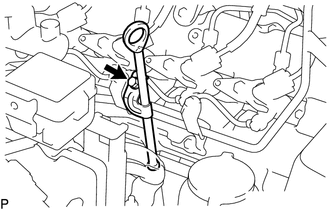
Remove the bolt and No. 2 engine oil level dipstick guide.
Remove the O-ring from the No. 2 engine oil level dipstick guide.
23271H 13.DISCONNECT NO. 1 AND NO. 2 FUEL HOSES
44769 14.REMOVE VACUUM RESERVOIR CONNECT TUBE
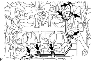
Slide the 2 clamps and disconnect the 2 vacuum hoses.
Remove the 4 bolts and vacuum reservoir connect tube.
82122 15.DISCONNECT NO. 2 ENGINE WIRE
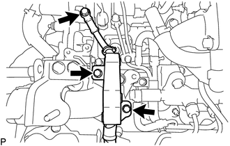
Remove the 3 bolts and disconnect the No. 2 engine wire.
44761 16.REMOVE VACUUM PUMP TO CONNECTOR TUBE
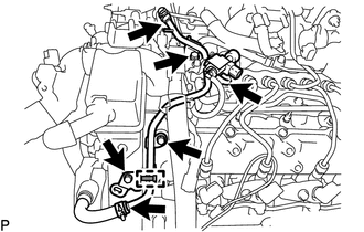
Disconnect the engine wire clamp.
Disconnect the No. 2 vacuum transmitting hose assembly.
Slide the 2 clamps and disconnect the 2 vacuum hoses.
Remove the 3 bolts and vacuum pump to connector tube.
25850 17.REMOVE ELECTRIC VACUUM REGULATING VALVE ASSEMBLY
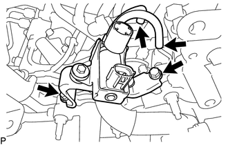
Disconnect the electric vacuum regulating valve connector.
Disconnect the 2 vacuum hoses.
Remove the 2 bolts and electric vacuum regulating valve assembly.
16288 18.REMOVE NO. 4 WATER BY-PASS PIPE
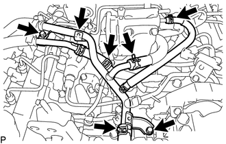
Slide the 3 clamps and disconnect the inlet water hose, No. 4 water by-pass hose and No. 12 water by-pass hoses.
Remove the 2 bolts, nut and No. 4 water by-pass pipe.
Slide the clamp and remove the No. 2 water by-pass pipe.
25800 19.REMOVE ELECTRIC EGR CONTROL VALVE ASSEMBLY
23243C 20.DISCONNECT FUEL PUMP MOTOR WIRE
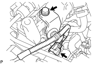
Remove the bolt and No. 1 fuel pump bracket.
Disconnect the fuel pump motor connector.
82121 21.DISCONNECT ENGINE WIRE
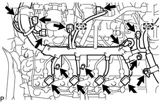
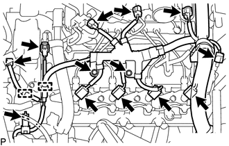
RH Side:
Disconnect the 6 connectors.
Disconnect the 4 fuel injector connectors.
Remove the 4 bolts and nut.
Detach the 2 clamps and disconnect the engine wire.
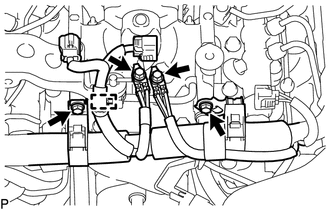
LH Side:
Disconnect the 6 connectors.
Disconnect the 4 fuel injector connectors.
Remove the 3 bolts.
Detach the 2 clamps and disconnect the engine wire.
Rear Side:
Remove the 2 bolts and disconnect the 2 ground wires.
Detach the clamp from the No. 3 intercooler support bracket.
Remove the 2 bolts and disconnect the 2 wire harness brackets.
23265 22.REMOVE NO. 1 GAS FILTER
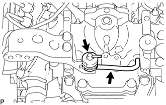
Disconnect the hose from the intake pipe.
Remove the No. 1 gas filter.
17947B 23.REMOVE NO. 3 INTERCOOLER SUPPORT BRACKET
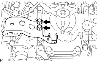
Remove the 2 bolts and No. 3 intercooler support bracket.
23706 24.REMOVE NO. 6 INJECTION PIPE SUB-ASSEMBLY
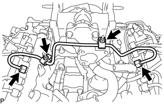
- NOTICE:
-
After removing the fuel pipe, to prevent dirt or foreign objects from entering the pipe inlet, cover the common rail with electrical tape. Also protect the injector inlets with electrical tape or plastic bags.
Remove the 2 nuts and 2 injection pipe clamps.
Using a 17 mm union nut wrench, loosen the union nuts and remove the injection pipe.
25.REMOVE INJECTION PIPE RH
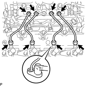
- NOTICE:
-
After removing the fuel pipe, to prevent dirt or foreign objects from entering the pipe inlet, cover the common rail with electrical tape. Also protect the injector inlets with electrical tape or plastic bags.
Using a 17 mm union nut wrench, loosen the union nuts and remove the 4 injection pipes.
26.REMOVE INJECTION PIPE LH
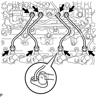
- NOTICE:
-
After removing the fuel pipe, to prevent dirt or foreign objects from entering the pipe inlet, cover the common rail with electrical tape. Also protect the injector inlets with electrical tape or plastic bags.
Using a 17 mm union nut wrench, loosen the union nuts and remove the 4 injection pipes.
23763 27.REMOVE NO. 3 NOZZLE LEAKAGE PIPE
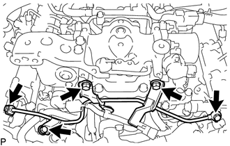
Remove the 2 injector hollow screws, 3 bolts, No. 3 nozzle leakage pipe and 2 gaskets.
17113 28.REMOVE INTAKE PIPE
23812D 29.REMOVE NO. 2 FUEL PIPE SUB-ASSEMBLY
- NOTICE:
-
After removing an injection pipe, to prevent dirt or foreign objects from entering the common rail holes, cover the holes with protective tape.
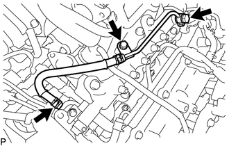
Disconnect the No. 4 fuel hose from the fuel filter to injection pump fuel pipe sub-assembly.
Remove the union bolt and gasket.
Remove the bolt and No. 2 fuel pipe sub-assembly.
23765 30.REMOVE NO. 5 NOZZLE LEAKAGE PIPE
23801L 31.REMOVE FUEL FILTER TO INJECTION PUMP FUEL PIPE SUB-ASSEMBLY
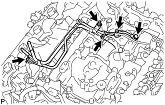
Remove the bolt and No. 2 injection pipe clamp.
Disconnect the fuel hose.
Remove the union bolt, nut, bolt, fuel filter to injection pump fuel pipe sub-assembly and gasket.
23705 32.REMOVE NO. 5 INJECTION PIPE SUB-ASSEMBLY
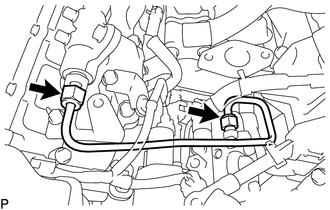
Using a union nut wrench, remove the No. 5 injection pipe.
- NOTICE:
-
After removing an injection pipe, to prevent dirt or foreign objects from entering the common rail hole or injection pump hole, cover the holes with protective tape.
23820A 33.REMOVE COMMON RAIL RH
23810A 34.REMOVE COMMON RAIL LH
17114D 35.REMOVE NO. 3 INTAKE MANIFOLD
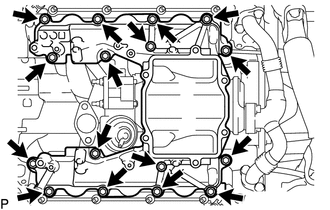
Remove the 16 bolts, 2 gaskets and No. 3 intake manifold.
36.REMOVE EGR COOLER
23901H 37.REMOVE FUEL TUBE SUB-ASSEMBLY
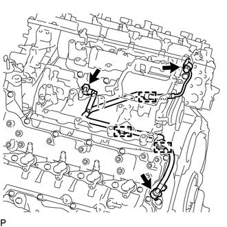
Disconnect the 2 fuel tube connectors (See page Engine / Hybrid System>1VD-FTV (FUEL)>FUEL SYSTEM(w/ DPF)>PRECAUTION).
Remove the No. 2 check valve.
Detach the 3 clamps and remove the fuel tube.
16268 38.REMOVE NO. 1 WATER BY-PASS PIPE
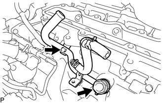
Remove the union bolt and gasket.
Remove the bolt and No. 1 water by-pass pipe.
23841C 39.REMOVE NO. 1 FUEL PIPE CLAMP
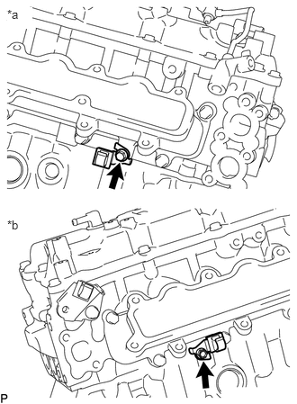
| *a | RH Side |
| *b | LH Side |
Remove the 2 bolts and 2 No. 1 fuel pipe clamps.
40.REMOVE STARTER HOSE BRACKET SUB-ASSEMBLY
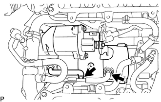
Disconnect the 2 starter hoses from the starter assembly and starter hose bracket sub-assembly.
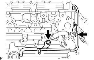
Remove the 2 bolts and starter hose bracket sub-assembly.
17111 41.REMOVE NO. 1 INTAKE MANIFOLD
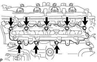
Remove the 8 bolts, No. 1 intake manifold and gasket.
17112 42.REMOVE NO. 2 INTAKE MANIFOLD
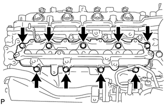
Remove the 9 bolts, No. 2 intake manifold and gasket.
43.REPLACE STUD BOLT
- HINT:
-
If a stud bolt is deformed or its threads are damaged, replace it.
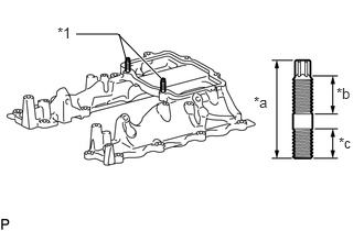
| *1 | Stud Bolt |
| *a | 42 mm (1.65 in.) |
| *b | 20 mm (0.787 in.) |
| *c | 13 mm (0.512 in.) |
For No. 3 Intake Manifold:
Using an E8 "TORX" wrench, replace the stud bolts.
- Torque:
- 6.0 N*m (61 kgf*cm, 53 in.*lbf)
44.REPLACE RING PIN
- HINT:
-
It is not necessary to remove a ring pin unless it is being replaced.
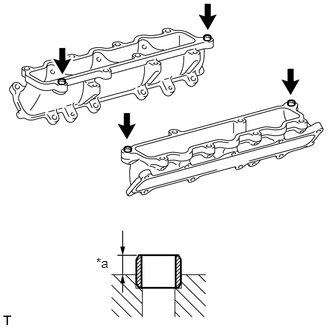
| *a | Protrusion height |
For No. 1 and No. 2 Intake Manifold:
Replace the ring pins.
- Standard protrusion:
-
4.4 to 5.6 mm (0.173 to 0.222 in.)