SUPPLEMENTAL RESTRAINT SYSTEMS POP UP HOOD SENSOR INSTALLATION
CAUTION / NOTICE / HINT
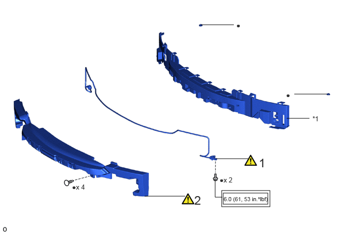
| Procedure | Part Name Code | 
|

|

|
|
|---|---|---|---|---|---|
| 1 | PEDESTRIAN DETECTION CHAMBER ASSEMBLY | 52620 | ( ) |
- | - |
| 2 | FRONT BUMPER ENERGY ABSORBER | 52611 | ()
|
- | - |
| *1 | NO. 2 FRONT BUMPER MOUNTING BRACKET | - | - |

|
Tightening torque for "Major areas involving basic vehicle performance such as moving/turning/stopping": N*m (kgf*cm, ft.*lbf) | ● | Non-reusable part |
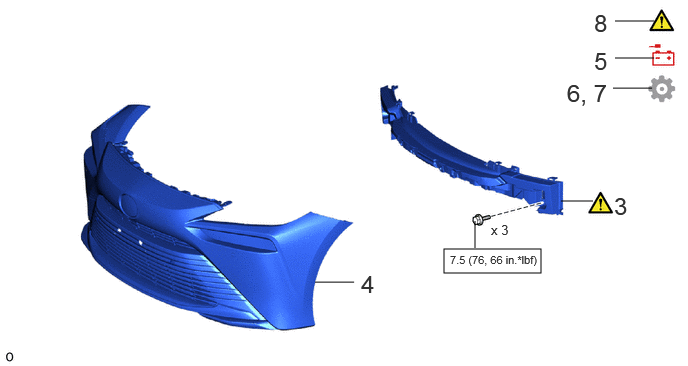
| Procedure | Part Name Code |
|
|
|
|
|---|---|---|---|---|---|
| 3 | FRONT BUMPER ENERGY ABSORBER SUB-ASSEMBLY | - | ()
|
- | - |
| 4 | FRONT BUMPER ASSEMBLY | - | - | - | - |
| 5 | NEGATIVE AUXILIARY BATTERY TERMINAL | - | - | - | - |
| 6 | INITIALIZATION AFTER RECONNECTING AUXILIARY BATTERY TERMINAL | - | - | - | ()
|
| 7 | PERFORM DIAGNOSTIC SYSTEM CHECK | - | - | - | ()
|
| 8 | CHECK SRS WARNING LIGHT | - | ()
|
- | - |

|
N*m (kgf*cm, ft.*lbf): Specified torque | - | - |
CAUTION / NOTICE / HINT
PROCEDURE

 52620
1.INSTALL PEDESTRIAN DETECTION CHAMBER ASSEMBLY
|
|
|
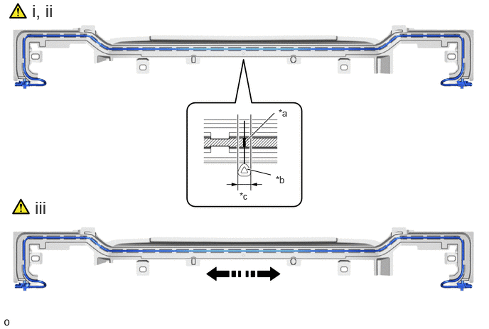
| *a | Center Mark of Pedestrian Detection Chamber | *b | Front Bumper Energy Absorber Positioning Standard |
| *c | 10 mm (0.394 in.) | - | - |

|
Install in this Direction | - | - |
Align the center mark of the pedestrian detection chamber with the front bumper energy absorber positioning standard and set the parts into place as shown in the illustration.
Check that the center mark of the pedestrian detection chamber is within 10 mm of the front bumper energy absorber positioning standard.
Starting from the front bumper energy absorber positioning standard and working outward, install the pedestrian detection chamber to the pedestrian detection chamber connection areas of the front bumper energy absorber.
52611
2.INSTALL FRONT BUMPER ENERGY ABSORBER
|
|
|
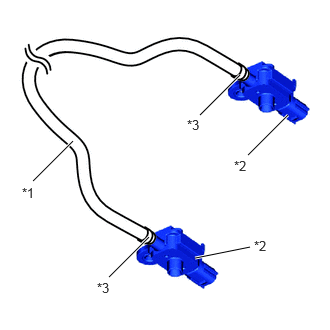
| *a | Breathing Filter | *b | Hook |
| *c | Guide | - | - |
|
|
Install in this Direction | - | - |
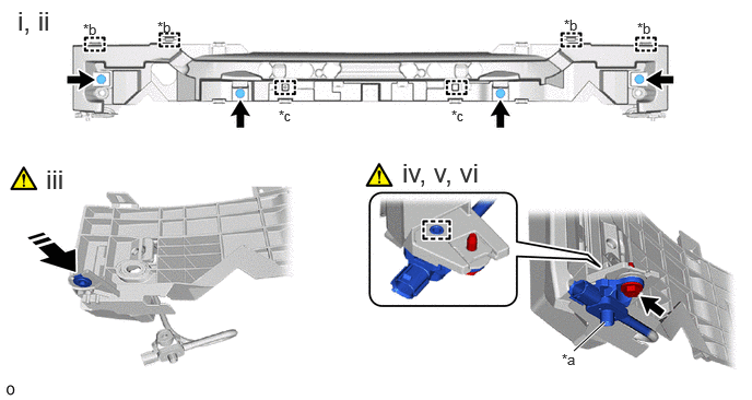
Attach the hook and guide to install the front bumper energy absorber.
Install the 4 clips.
Install the nut to the No. 2 front bumper mounting bracket.
- HINT:
-
Use the same procedure for the opposite side.
Check that the breathing filter of the pedestrian protection sensor.
- OK:
The breathing filter is not blocked by foreign matter or damaged.
Attach the guide and install the pedestrian protection to the front bumper energy absorber with a bolt so that the breathing filter points downward.
- Torque:
- 6.0 N*m (61 kgf*cm, 53 in.*lbf)
- HINT:
-
Use the same procedure for the opposite side.
Check that there is no looseness in the installation parts of the pedestrian detection chamber assembly.
3.INSTALL FRONT BUMPER ENERGY ABSORBER SUB-ASSEMBLY
|
|
Click here()
|
4.INSTALL FRONT BUMPER ASSEMBLY
5.CONNECT CABLE TO NEGATIVE AUXILIARY BATTERY TERMINAL
6. INITIALIZATION AFTER RECONNECTING AUXILIARY BATTERY TERMINAL
Click hereGeneral>SETUP>WHEN DISCONNECTING OR RECONNECTING BATTERY TERMINAL>AUTOMATIC LEARNING CHART
- HINT:
-
When disconnecting and reconnecting the auxiliary battery, there is an automatic learning function that completes learning when the respective system is used.
-
Click hereGeneral>SETUP>WHEN DISCONNECTING OR RECONNECTING BATTERY TERMINAL>AUTOMATIC LEARNING CHART
7. PERFORM DIAGNOSTIC SYSTEM CHECK
8.CHECK SRS WARNING LIGHT