POWER DISTRIBUTION INTEGRATION RELAY(for Front Side) REMOVAL
CAUTION / NOTICE / HINT
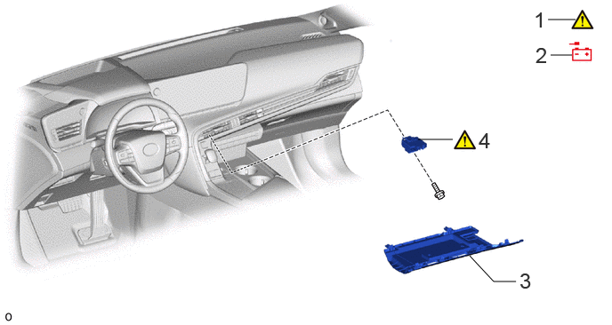
| Procedure | Part Name Code | 
|

|

|
|
|---|---|---|---|---|---|
| 1 | PRECAUTION | - | ( ) |
- | - |
| 2 | CABLE FROM NEGATIVE AUXILIARY BATTERY TERMINAL | - | - | - | - |
| 3 | NO. 2 INSTRUMENT PANEL UNDER COVER SUB-ASSEMBLY | 55607 | - | - | - |
| 4 | NO. 1 SEMICONDUCTOR POWER INTEGRATION ECU | 82644A | ()
|
- | - |
CAUTION / NOTICE / HINT
The necessary procedures (adjustment, calibration, initialization, or registration) that must be performed after parts are removed, installed, or replaced during the No. 1 semiconductor power integration ECU removal/installation are shown below.
| Replaced Part or Performed Procedure | Necessary procedures | Effect/Inoperative Function when Necessary Procedure not Performed | Link |
|---|---|---|---|
| Disconnect cable from negative (-) auxiliary battery terminal | Memorize steering angle neutral point | Parking assist monitor system | ()
|
| Panoramic view monitor system | ()
|
- HINT:
- ·
When the cable is disconnected/reconnected to the auxiliary battery terminal, systems temporarily stop operating. However, each system has a function that completes learning the first time the system is used.
-Learning completes when vehicle is driven
Effect/Inoperative Function When Necessary Procedures are not Performed Necessary Procedures Link Lane tracing assist system Drive the vehicle straight ahead at 35 km/h (22 mph) or more for 5 seconds or more. ( )
Pre-collision system Adaptive high beam system
-Learning completes when vehicle is operated normally
Effect/Inoperative Function When Necessary Procedures are not Performed Necessary Procedures Link Air conditioning system After the ignition switch is turned to ON, the servo motor and expansion valve standard position is recognized. -
·Use the same procedure for RHD and LHD vehicles.
·The procedure listed below is for LHD vehicles.
PROCEDURE

 1. PRECAUTION
|
|
|
2.DISCONNECT CABLE FROM NEGATIVE AUXILIARY BATTERY TERMINAL
55607
3.REMOVE NO. 2 INSTRUMENT PANEL UNDER COVER SUB-ASSEMBLY
82644
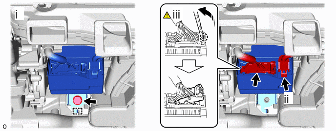
4.REMOVE NO. 1 SEMICONDUCTOR POWER INTEGRATION ECU
|
|
|

|
Remove in this Direction | - | - |
Remove the bolt, detach the guide and remove the No. 1 semiconductor power integration ECU.
Disconnect the power source connector.
- NOTICE:
-
First disconnect the power supply connector.
Using a thin-bladed screwdriver with its tip wrapped with protective tape, detach the claw and disconnect the lever connector.