EXTERIOR PANELS / TRIM FRONT FENDER REASSEMBLY
CAUTION / NOTICE / HINT
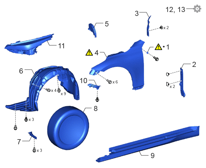
| Procedure | Part Name Code | 
|

|

|
|
|---|---|---|---|---|---|
| 1 | FRONT FENDER SEAL LH | 53883B | ( ) |
- | - |
| 2 | FRONT SIDE PANEL NO. 2 PROTECTOR LH | 53824B | - | - | - |
| 3 | FRONT FENDER SIDE PANEL PROTECTOR LH | 53828K | - | - | - |
| 4 | FRONT FENDER SUB-ASSEMBLY LH | 53802 | ()
|
- | - |
| 5 | FRONT SIDE AIR GUIDE | 53153E | - | - | - |
| 6 | FRONT FENDER SPLASH SHIELD SUB-ASSEMBLY LH | 53806C | - | - | - |
| 7 | FRONT WHEEL OPENING EXTENSION PAD LH | 53852B | - | - | - |
| 8 | WHEEL ASSEMBLY | - | - | - | - |
| 9 | ROCKER PANEL MOULDING ASSEMBLY LH | - | - | - | - |
| 10 | FRONT BUMPER SIDE SUPPORT LH | 52116A | - | - | - |
| 11 | HEADLIGHT ASSEMBLY LH | - | - | - | - |
| 12 | ADJUST FRONT DOOR PANEL SUB-ASSEMBLY LH | 67002 | - | - | ()
|
| 13 | ADJUST HOOD SUB-ASSEMBLY | 53301 | - | - | ()
|
| ● | Non-reusable part | - | - |
- HINT:
- ·
Use the same procedure for the RH and LH sides.
·The procedure described below is for the LH side.
CAUTION / NOTICE / HINT
- HINT:
-
A bolt without a torque specification is shown in the standard bolt chart.
-
Click hereGeneral>SPECIFICATIONS>STANDARD BOLT>SPECIFIED TORQUE FOR STANDARD BOLTS
PROCEDURE

 53883B
1.INSTALL FRONT FENDER SEAL LH
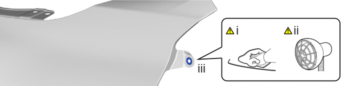
Clean the front fender sub-assembly LH surface:
1. When reusing the front fender sub-assembly LH, remove remaining double-sided tape from the front fender sub-assembly LH.
2. Using a heat light, heat the front fender sub-assembly LH surface.
- Standard Value:
Part Temperature Front Fender Sub-assembly LH 40 to 60°C (104 to 140°F) Front Fender Seal LH 20 to 30°C (68 to 86°F)
- CAUTION:
-
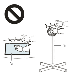 2.365,2 2.698,2 false 0.5,2.333 0.5,2.667 true 0.427,2.708 0.74,2.865 0.313,0.156 10 false *a 2.76,1.927 3.073,2.083 0.313,0.156 10 false *b
*a Heated Part *b Heat Light
- ·
Do not touch the heat light and heated parts.
·Touching the heat light may result in burns.
·Touching heated parts for a long time may result in burns.
- NOTICE:
-
Do not heat the front fender sub-assembly LH excessively.
3. Remove any remaining double-sided tape from the front fender sub-assembly LH and wipe off any tape adhesive residue with cleaner.
4. Clean the installation area surface.
- NOTICE:
- ·
Installing the front fender seal LH with some double-sided tape remaining may cause poor adhesion. Perform this procedure until the tape is sufficiently removed.
·Make sure to use a cloth when removing. Using a screwdriver, etc., may cause damage and poor adhesion.
·Also, clean a new front fender sub-assembly LH surface.
Using a heat light, heat the front fender sub-assembly LH and a new front fender seal LH.
- NOTICE:
-
Do not heat the front fender sub-assembly LH and a new front fender seal LH excessively.
Install the front fender seal LH in the position shown in the illustration.
- NOTICE:
-
The application strength of the front fender seal LH will weaken if reapplied. If reapplication is necessary, be sure to replace it with a new one.
- HINT:
-
Apply pressure so that it does not lift up from the front fender sub-assembly LH.
53824B
2.INSTALL FRONT SIDE PANEL NO. 2 PROTECTOR LH
53828K
3.INSTALL FRONT FENDER SIDE PANEL PROTECTOR LH
53802
4.INSTALL FRONT FENDER SUB-ASSEMBLY LH
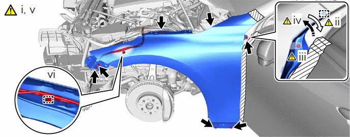

|
Install in this Direction | 
|
Bolt |

|
Fold Back | - | - |
Temporarily install the front fender sub-assembly LH with 6 bolts.
Detach the guide and fold back the front fender side panel protector LH.
Install the bolt.
Attach the guide and install the front fender side panel protector LH.
Tighten the 6 bolts.
Attach the clamp.
53153E
5.INSTALL FRONT SIDE AIR GUIDE
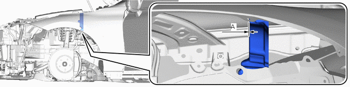
- Standard Measurement:
Area Measurement Area Measurement A -10.0 to 10.0 mm (-0.394 to 0.394 in.) - -
53806C
6.INSTALL FRONT FENDER SPLASH SHIELD SUB-ASSEMBLY LH
53852B
7.INSTALL FRONT WHEEL OPENING EXTENSION PAD LH
8.INSTALL WHEEL ASSEMBLY
9.INSTALL ROCKER PANEL MOULDING ASSEMBLY LH
52116A
10.INSTALL FRONT BUMPER SIDE SUPPORT LH
11.INSTALL HEADLIGHT ASSEMBLY LH
67002
12.ADJUST FRONT DOOR PANEL SUB-ASSEMBLY LH
53301
13.ADJUST HOOD SUB-ASSEMBLY