Home › Engine / Hybrid System › INTAKE / EXHAUST › AIR CONTROL VALVE
RM37H0E _51 Engine / Hybrid System _095594 INTAKE / EXHAUST _0448989 AIR CONTROL VALVE A

INTAKE / EXHAUST  AIR CONTROL VALVE  INSTALLATION  


CAUTION / NOTICE / HINT
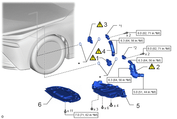
COMPONENTS (INSTALLATION)
A478620N02
5.521,1.229 6.51,1.438 0.99,0.208 5.938,1.865 6.917,2.063 0.979,0.198 5.542,2.333 6.563,2.542 1.021,0.208 5.365,3.615 6.344,3.823 0.979,0.208 4.333,3.135 5.313,3.344 0.979,0.208 4.823,1.542 5.833,1.74 1.01,0.198 3,4.552 3.969,4.771 0.969,0.219 4.01,2.344 4.135,2.344 4.135,2.344 4.313,2.469 false 3.5,2.5 3.281,1.813 false 4.198,3.063 4.344,3.063 4.344,3.063 4.677,2.438 false 3.354,2.51 3.5,2.51 3.5,2.51 3.979,1.615 false 4.354,3.052 4.021,2.604 false 3.615,1.479 3.729,0.969 3.729,0.969 3.875,0.969 false 4.323,1.396 4.594,1.031 4.594,1.031 4.74,1.031 false 5,2.26 5.208,1.927 5.208,1.927 5.354,1.927 false 5.521,2.865 5.802,2.708 5.802,2.708 5.969,2.708 false 5.802,2.125 5.802,1.958 5.802,1.958 5.927,1.958 false 5.51,1.323 5.177,1.323 false 5.802,3.615 5.802,3.115 false 5.219,2.438 5.531,2.438 true 5.229,2.771 4.802,2.771 4.802,2.771 4.802,3.125 false 4.813,1.635 4.438,1.635 true 4.583,2.177 4.729,2.177 4.729,2.177 4.729,1.635 true 5.094,3.927 5.25,4.25 5.25,4.25 5.417,4.25 false 1.75,4.219 1.896,4.219 1.896,4.219 2.125,3.927 false 4.51,2.042 4.323,2.042 false 2.635,4.563 2.635,4.656 2.635,4.656 2.99,4.656 false 3.875,2.208 4.156,2.563 0.281,0.354 18 false 1 6.333,2.563 6.615,2.917 0.281,0.354 18 false 2 4.208,0.844 4.49,1.198 0.281,0.354 18 false 3 4.135,1.927 4.417,2.281 0.281,0.354 18 false 4 5.406,1.854 5.688,2.208 0.281,0.354 10 false *2 4.813,0.969 5.094,1.323 0.281,0.354 10 false *1 4.01,3.021 4.26,3.229 0.25,0.208 10 false ● 3.156,2.469 3.302,2.646 0.146,0.177 10 true ● 5.875,2.104 6.188,2.302 0.313,0.198 10 false x 2 5.115,1.344 5.427,1.542 0.313,0.198 10 false x 2 5.573,1.271 6.542,1.448 0.969,0.177 8 false 8.0 (82, 71 in.*lbf) 5.604,2.375 6.604,2.552 1,0.177 8 false 6.3 (64, 56 in.*lbf) 5.406,3.656 6.406,3.844 1,0.188 8 false 5.0 (51, 44 in.*lbf) 5.521,4.135 5.802,4.49 0.281,0.354 18 false 5 1.542,4.083 1.823,4.438 0.281,0.354 18 false 6 3.792,4.344 4.104,4.542 0.313,0.198 10 false x 3 4.615,4.198 4.927,4.396 0.313,0.198 10 false x 4 4.229,4.292 4.542,4.49 0.313,0.198 10 false x 6 2.719,4.406 3.031,4.604 0.313,0.198 10 false x 11 3.042,4.583 4.073,4.75 1.031,0.167 8 false 7.0 (71, 62 in.*lbf) 4.385,3.167 5.385,3.344 1,0.177 8 false 6.3 (64, 56 in.*lbf) 4.885,1.573 5.885,1.75 1,0.177 8 false 6.3 (64, 56 in.*lbf) 5.979,1.896 6.948,2.073 0.969,0.177 8 false 8.0 (82, 71 in.*lbf)

Procedure Part Name Code
Z101186

Z101188

Z101187

1 FC AIR PRESSURE REGULATOR ASSEMBLY (AIR PRESSURE REGULATING VALVE) 17C10 (Click here) - -
2 FC STACK AIR OUTLET HOSE ASSEMBLY 17D10 (Click here) - -
3 FC AIR PRESSURE REGULATOR ASSEMBLY (AIR SEALING VALVE) 17C10 (Click here) - -
4 FC STACK AIR INLET HOSE 17B21 (Click here) - -
5 REAR NO. 4 FLOOR BOARD SUB-ASSEMBLY 58404B - - -
6 FRONT COMPARTMENT UNDER COVER ASSEMBLY 51420A - - -

*1 FC STACK AIR INLET PIPE ASSEMBLY *2 FC STACK AIR OUTLET PIPE ASSEMBLY
V100146

N*m (kgf*cm, ft.*lbf): Specified torque ● Non-reusable part

PROCEDURE

Hide 17C10 1.INSTALL FC AIR PRESSURE REGULATOR ASSEMBLY (AIR PRESSURE REGULATING VALVE)

a.
A478623C01
1.479,0.292 1.615,0.292 1.615,0.292 1.906,0.552 true 5.063,0.167 5.177,0.167 5.177,0.167 5.563,0.313 true 1.198,0.229 1.438,0.406 0.24,0.177 10 true *a 0.406,0.063 0.708,0.344 0.302,0.281 18 false i 4.865,0.083 5.104,0.26 0.24,0.177 10 true *a
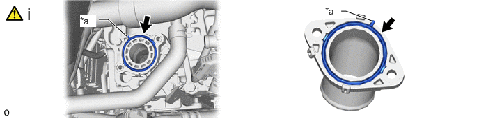
*a Protrusion - -


i.

Install the 2 No. 5 FC stack air gaskets to the FC stack air outlet pipe assembly and FC stack air outlet with the protrusions of the No. 5 FC stack air gasket oriented as shown in the illustration.


b.
A478562N01
0.115,0.052 0.521,0.396 0.406,0.344 18 false i, ii

i.

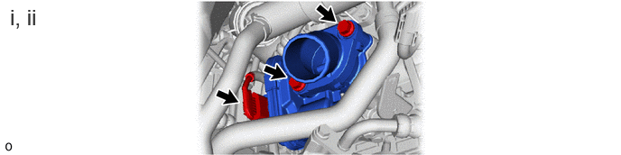
Install the FC stack air outlet pipe assembly and FC air pressure regulator assembly (air pressure regulating valve) with the 2 bolts.

Torque:
8.0 N*m (82 kgf*cm, 71 in.*lbf)


ii.

Connect the connector.


Hide 17D10 2.INSTALL FC STACK AIR OUTLET HOSE ASSEMBLY

Z101186

Click here(Click here)

Hide 17C10 3.INSTALL FC AIR PRESSURE REGULATOR ASSEMBLY (AIR SEALING VALVE)

Z101186

NOTICE:
·

Do not touch the mesh of the air particulate filter.

·

If the air particulate filter is removed from the FC stack air inlet pipe assembly or is deformed, replace the FC stack air inlet pipe assembly.


a.
A478624C02
1.438,0.281 1.573,0.281 1.573,0.281 1.865,0.542 true 4.594,0.156 4.708,0.156 4.708,0.156 5.26,0.219 true 5.396,0.958 6.094,0.542 6.094,0.542 6.271,0.542 true 1.198,0.229 1.438,0.406 0.24,0.177 10 true *a 0.406,0.063 0.708,0.344 0.302,0.281 18 false i 4.385,0.083 4.625,0.26 0.24,0.177 10 true *a 6.365,0.469 6.604,0.646 0.24,0.177 10 true *1
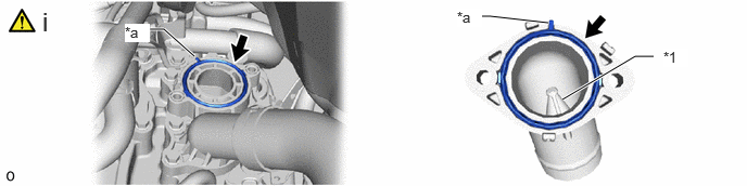
*1 Air Particulate Filter - -
*a Protrusion - -


i.

Install the 2 No. 5 FC stack air gaskets to the FC stack air inlet pipe assembly and FC stack air and water inlet with the protrusions of the No. 5 FC stack air gasket oriented as shown in the illustration.
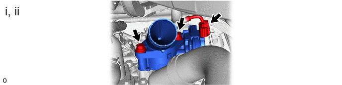


b.
A478559N01
0.104,0.083 1.208,0.438 1.104,0.354 18 false i, ii

i.

Install the FC stack air inlet pipe assembly and FC air pressure regulator assembly (air sealing valve) with the 2 bolts.

Torque:
8.0 N*m (82 kgf*cm, 71 in.*lbf)


ii.

Connect the connector.


Hide 17B21 4.INSTALL FC STACK AIR INLET HOSE

Z101186

Click here(Click here)

Hide 58404B 5.INSTALL REAR NO. 4 FLOOR BOARD SUB-ASSEMBLY

Hide 51420A 6.INSTALL FRONT COMPARTMENT UNDER COVER ASSEMBLY