STEERING COLUMN TILT AND TELESCOPIC MANUAL SWITCH REMOVAL
CAUTION / NOTICE / HINT
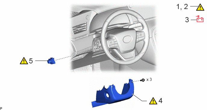
| Procedure | Part Name Code | 
|

|

|
|
|---|---|---|---|---|---|
| 1 | CUSTOMIZE POWER TILT AND POWER TELESCOPIC STEERING COLUMN SYSTEM | - | ( ) |
- | - |
| 2 | PRECAUTION | - | ()
|
- | - |
| 3 | DISCONNECT CABLE FROM NEGATIVE AUXILIARY BATTERY TERMINAL | - | - | - | - |
| 4 | LOWER STEERING COLUMN COVER | 45287 | ()
|
- | - |
| 5 | TILT AND TELESCOPIC SWITCH | 89235A | ()
|
- | - |
CAUTION / NOTICE / HINT
The necessary procedures (adjustment, calibration, initialization, or registration) that must be performed after parts are removed, installed, or replaced during the tilt and telescopic manual switch removal/installation are shown below.
- Necessary Procedure After Parts Removed/Installed/Replaced:
Replacement Part or Procedure Necessary Procedures Effects/Inoperative when not Performed Link Disconnect cable from negative auxiliary battery terminal Memorize steering angle neutral point Parking assist monitor system ( )
Panoramic view monitor system ( )
- HINT:
-
When the cable is disconnected/reconnected to the auxiliary battery terminal, systems temporarily stop operating. However, each system has a function that completes learning the first time the system is used.
- ·
Learning completes when vehicle is driven
Effect/Inoperative Function When Necessary Procedures are not Performed Necessary Procedures Link Lane tracing assist system Drive the vehicle straight ahead at 35 km/h (22 mph) or more for 5 seconds or more. ( )
Pre-collision system Adaptive high beam system
·Learning completes when vehicle is operated normally
Effect/Inoperative Function When Necessary Procedures are not Performed Necessary Procedures Link Air conditioning system After the ignition switch is turned to ON, theservo motor and expansion valve standardposition is recognized. -
·Use the same procedure for RHD and LHD vehicles.
·The procedure listed below is for LHD vehicles.
PROCEDURE

 1. CUSTOMIZE POWER TILT AND POWER TELESCOPIC STEERING COLUMN SYSTEM
|
|
Click here()
|
2. PRECAUTION
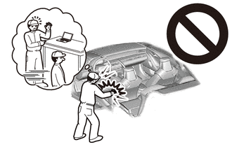
- CAUTION:
-
-
Be sure to read Precaution thoroughly before servicing.
-
Click hereVehicle Interior>SUPPLEMENTAL RESTRAINT SYSTEMS>AIRBAG SYSTEM>PRECAUTION
- NOTICE:
-
After turning the ignition switch off, waiting time may be required before disconnecting the cable from the negative (-) auxiliary battery terminal.
-
Click hereGeneral>INTRODUCTION>REPAIR INSTRUCTION>PRECAUTION
3.DISCONNECT CABLE FROM NEGATIVE AUXILIARY BATTERY TERMINAL
45287
4.REMOVE LOWER STEERING COLUMN COVER
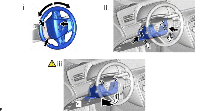
| *a | Felt | - | - |

|
Push Area | 
|
Remove in this Direction (1) |

|
Remove in this Direction (2) | 
|
Remove in this Direction (3) |
Turn the steering wheel and remove the 3 screws.
Press the part in the direction of the arrow shown in the illustration to detach the claw.
Detach the 2 claws and remove the lower steering column cover in the direction of the arrow shown in the illustration.
- NOTICE:
- ·
Do not damage the tilt and telescopic switch.
·Do not damage the felt part
89235A
5.REMOVE TILT AND TELESCOPIC SWITCH
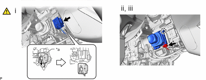
| *a | Slider | - | - |
Slide the slider to release the lock, and then disconnect the yellow airbag connector from the spiral cable with sensor sub-assembly.
- HINT:
-
Refer to How to Connect or Disconnect Airbag Connector:
Disconnect the tilt and telescopic connector from the tilt and telescopic switch.
Disengage the claw and pull out the tilt and telescopic switch.