STEERING COLUMN STEERING COLUMN ASSEMBLY(for Manual Tilt and Manual Telescopic Steering Column) INSTALLATION
CAUTION / NOTICE / HINT
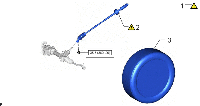
| Procedure | Part Name Code | 
|

|

|
|
|---|---|---|---|---|---|
| 1 | ALIGN FRONT WHEELS FACING STRAIGHT AHEAD | - | - | - | - |
| 2 | NO. 2 STEERING INTERMEDIATE SHAFT ASSEMBLY | 45260 | ( ) |
- | - |
| 3 | FRONT WHEEL LH | - | - | - | - |

|
Tightening torque for "Major areas involving basic vehicle performance such as moving/turning/stopping": N*m (kgf*cm, ft.*lbf) | - | - |
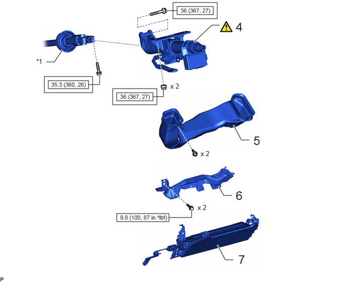
| Procedure | Part Name Code |
|
|
|
|
|---|---|---|---|---|---|
| 4 | STEERING COLUMN ASSEMBLY | 45250 | ()
|
- | - |
| 5 | NO. 2 HEATER TO REGISTER DUCT | 55844 | - | - | - |
| 6 | AIR DUCT SUB-ASSEMBLY | - | - | - | - |
| 7 | LOWER NO. 1 INSTRUMENT PANEL AIR BAG ASSEMBLY | 73900 | - | - | - |
| *1 | NO. 2 STEERING INTERMEDIATE SHAFT ASSEMBLY | - | - |
|
|
Tightening torque for "Major areas involving basic vehicle performance such as moving/turning/stopping": N*m (kgf*cm, ft.*lbf) | 
|
N*m (kgf*cm, ft.*lbf): Specified torque |
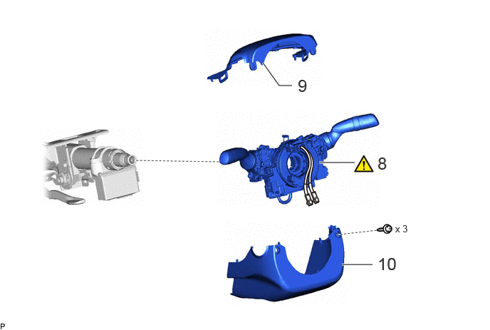
| Procedure | Part Name Code |
|
|
|
|
|---|---|---|---|---|---|
| 8 | TURN SIGNAL SWITCH ASSEMBLY WITH SPIRAL CABLE SUB-ASSEMBLY | - | ()
|
- | - |
| 9 | UPPER STEERING COLUMN COVER | 45286B | - | - | - |
| 10 | LOWER STEERING COLUMN COVER | 45287 | - | - | - |
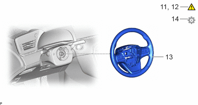
| Procedure | Part Name Code |
|
|
|
|
|---|---|---|---|---|---|
| 11 | ALIGN FRONT WHEELS FACING STRAIGHT AHEAD | - | - | - | - |
| 12 | INSPECT AND ADJUST SPIRAL CABLE SUB-ASSEMBLY | 84306 | ()
|
- | - |
| 13 | STEERING WHEEL ASSEMBLY | 45100 | - | - | - |
| 14 | INITIALIZATION AFTER RECONNECTING AUXILIARY BATTERY TERMINAL | - | - | - | ()
|
| 15 | PERFORM INITIALIZATION | - | - | - | ()
|
CAUTION / NOTICE / HINT
- HINT:
- ·
Use the same procedure for RHD and LHD vehicles.
·The procedure listed below is for LHD vehicles.
PROCEDURE

 1.ALIGN FRONT WHEELS FACING STRAIGHT AHEAD
45260
2.INSTALL NO. 2 STEERING INTERMEDIATE SHAFT ASSEMBLY
3.INSTALL FRONT WHEEL LH
45250
4.INSTALL STEERING COLUMN ASSEMBLY
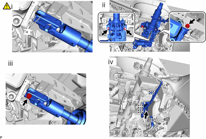
| *a | Matchmark | - | - |
Install the steering column assembly to the No. 2 steering intermediate shaft assembly.
Install the steering column assembly with the 2 nuts and bolt.
- Torque:
- 36 N*m (367 kgf*cm, 27 ft.*lbf)
- NOTICE:
-
Temporarily tighten the bolt, and then fully tighten the bolt and 2 nuts in the order of 2 nuts and bolt.
Install the bolt.
- Torque:
- 35.3 N*m (360 kgf*cm, 26 ft.*lbf)
Connect each connector and engage each wire harness clamp to the steering column assembly.
55844
5.INSTALL NO. 2 HEATER TO REGISTER DUCT
6.INSTALL AIR DUCT SUB-ASSEMBLY
73900
7.INSTALL LOWER NO. 1 INSTRUMENT PANEL AIR BAG ASSEMBLY
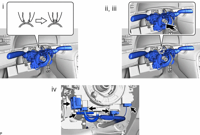
8.INSTALL TURN SIGNAL SWITCH ASSEMBLY WITH SPIRAL CABLE SUB-ASSEMBLY
|
|
|

|
Install in this Direction | - | - |
Using pliers, support the band clamp while loosened and set the turn signal switch assembly with spiral cable sub-assembly.
Engage the claw to install the turn signal switch assembly with spiral cable sub-assembly to the steering column assembly as shown in the illustration.
Tighten the band clamp.
Connect each connector to the turn signal switch assembly with spiral cable sub-assembly.
45286B
9.INSTALL UPPER STEERING COLUMN COVER
45287
10.INSTALL LOWER STEERING COLUMN COVER
11.ALIGN FRONT WHEELS FACING STRAIGHT AHEAD
84306
12.INSPECT AND ADJUST SPIRAL CABLE SUB-ASSEMBLY
|
|
Click here()
|
45100
13.INSTALL STEERING WHEEL ASSEMBLY
14. INITIALIZATION AFTER RECONNECTING AUXILIARY BATTERY TERMINAL
Click hereGeneral>SETUP>WHEN DISCONNECTING OR RECONNECTING BATTERY TERMINAL>WORK PROCEDURE
- HINT:
-
When disconnecting and reconnecting the battery, there is an automatic learning function that completes learning when the respective system is used.
-
Click hereGeneral>SETUP>WHEN DISCONNECTING OR RECONNECTING BATTERY TERMINAL>AUTOMATIC LEARNING CHART
15.PERFORM INITIALIZATION