WINDOW / GLASS POWER WINDOW CONTROL SYSTEM B2312 Power Window Switch Malfunction
DESCRIPTION
The power window regulator motor assemblies are operated by the multiplex network master switch assembly, power window regulator switch assembly or rear power window regulator switch assemblies. The power window regulator motor assemblies have motor, regulator and ECU functions.
This DTC is output when an ECU built into a power window regulator motor assembly and multiplex network master switch assembly determines that the multiplex network master switch assembly, power window regulator switch assembly or rear power window regulator switch assembly is stuck.
| DTC No. | Detection Item | DTC Detection Condition | Trouble Area | DTC Output from | Priority |
|---|---|---|---|---|---|
| B2312 | Power Window Switch Malfunction | ·
Multiplex network master switch assembly stuck (except driver door) ·
Multiplex network master switch assembly held in same position for more than 20 seconds (except driver door) |
Multiplex network master switch assembly | Master Switch | A |
| DTC No. | Detection Item | DTC Detection Condition | Trouble Area | DTC Output from | Priority |
|---|---|---|---|---|---|
| B2312 | Power Window Switch Malfunction | ·
Front power window regulator motor assembly LH stuck (for LHD) ·
Front power window regulator motor assembly RH stuck (for RHD) ·
Multiplex network master switch assembly held in same position for more than 20 seconds |
·
Multiplex network master switch assembly ·
Front power window regulator motor assembly LH (for LHD) ·
Front power window regulator motor assembly RH (for RHD) ·
Harness or connector |
D-Door Motor | A |
| DTC No. | Detection Item | DTC Detection Condition | Trouble Area | DTC Output from | Priority |
|---|---|---|---|---|---|
| B2312 | Power Window Switch Malfunction | ·
Power window regulator switch assembly stuck ·
Power window regulator switch assembly held in same position for more than 20 seconds |
·
Power window regulator switch assembly ·
Front power window regulator motor assembly RH (for LHD) ·
Front power window regulator motor assembly LH (for RHD) ·
Harness or connector |
P-Door Motor | A |
| DTC No. | Detection Item | DTC Detection Condition | Trouble Area | DTC Output from | Priority |
|---|---|---|---|---|---|
| B2312 | Power Window Switch Malfunction | ·
Rear power window regulator switch assembly LH stuck ·
Rear power window regulator switch assembly LH held in same position for more than 20 seconds |
·
Rear power window regulator switch assembly LH ·
Rear power window regulator motor assembly LH ·
Harness or connector |
RL-Door Motor | A |
| DTC No. | Detection Item | DTC Detection Condition | Trouble Area | DTC Output from | Priority |
|---|---|---|---|---|---|
| B2312 | Power Window Switch Malfunction | ·
Rear power window regulator switch assembly RH stuck ·
Rear power window regulator switch assembly RH held in same position for more than 20 seconds |
·
Rear power window regulator switch assembly RH ·
Rear power window regulator motor assembly RH ·
Harness or connector |
RR-Door Motor | A |
WIRING DIAGRAM
CAUTION / NOTICE / HINT
- NOTICE:
- ·
DTC B2312 is stored in the multiplex network master switch assembly and in each power window regulator motor assembly.
·If a power window regulator motor assembly has been replaced with a new one, initialize the power window control system.
Click hereVehicle Exterior>WINDOW / GLASS>POWER WINDOW CONTROL SYSTEM>INITIALIZATION
·Inspect the fuses for circuits related to this system before performing the following procedure.
·The power window control system uses the LIN communication system. Inspect the communication function by following How to Proceed with Troubleshooting. Troubleshoot the power window control system after confirming that the communication system is functioning properly.
Click hereVehicle Exterior>WINDOW / GLASS>POWER WINDOW CONTROL SYSTEM>HOW TO PROCEED WITH TROUBLESHOOTING
- HINT:
-
If DTC B2312 is not output again after the DTC has been cleared, the DTC was output due to the switch being held.
PROCEDURE
Check the vehicle specifications.
- Result:
Result Proceed to for LHD A for RHD B
A
B
Check for DTCs.
- Body Electrical > Master Switch > Trouble Codes
- 50001 148
- Body Electrical > D-Door Motor > Trouble Codes
- 50001 124
- Body Electrical > P-Door Motor > Trouble Codes
- 50001 144
- Body Electrical > RL-Door Motor > Trouble Codes
- 50001 146
- Body Electrical > RR-Door Motor > Trouble Codes
- 50001 145
- Result:
Result Proceed to Any Master Switch DTCs in the table below are output A Any D-Door Motor DTCs in the table below are output B Any P-Door Motor DTCs in the table below are output C Any RL-Door Motor DTCs in the table below are output D Any RR-Door Motor DTCs in the table below are output E No DTCs in the table below are output F
| Malfunction Status | System | Related DTCs | |
|---|---|---|---|
| Power Window Switch Malfunction | Master Switch | B2312 | ON Switch Failure |
| D-Door Motor | B2312 | Master Switch of Driver side door Malfunction | |
| P-Door Motor | B2312 | Power Window Switch of Passenger side door Malfunction | |
| RL-Door Motor | B2312 | Power Window Switch of Rear Left side door Malfunction | |
| RR-Door Motor | B2312 | Power Window Switch of Rear Right side door Malfunction | |
A
B
C
D
E
F
Read the Data List according to the display on the GTS.
- Body Electrical > D-Door Motor > Data List
-
Tester Display Measurement Item Range Normal Condition Diagnostic Note D Door P/W Up SW Driver door power window manual up switch signal OFF or ON OFF: Driver door power window manual up switch not being operated
ON: Driver door power window manual up switch being operated-
- Body Electrical > D-Door Motor > Data List
-
Tester Display D Door P/W Up SW - 50003 124 2
- Result:
Result Proceed to The value of D Door P/W Up SW is OFF A None of the above conditions are met B
A
B
Read the Data List according to the display on the GTS.
- Body Electrical > D-Door Motor > Data List
-
Tester Display Measurement Item Range Normal Condition Diagnostic Note D Door P/W Down SW Driver door power window manual down switch signal OFF or ON OFF: Driver door power window manual down switch not being operated
ON: Driver door power window manual down switch being operated-
- Body Electrical > D-Door Motor > Data List
-
Tester Display D Door P/W Down SW - 50003 124 3
- Result:
Result Proceed to The value of D Door P/W Down SW is OFF A None of the above conditions are met B
A
B
Pre-procedure1
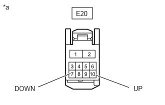
| *a | Front view of wire harness connector
(to Front Power Window Regulator Motor Assembly LH) |
Disconnect the front power window regulator motor assembly LH connector.
Procedure1
Measure the voltage according to the value(s) in the table below.
- Standard Voltage:
Tester Connection Switch Condition Specified Condition Click Location & Routing(E20)Location & Routingewd_type=routing;type=c;code=E20
Click Connector(E20)Body>Front Door Wire LH / Front Door Wire RH>Front Power Window Regulator Motor Assembly LHewd_type=component;type=c;code=E20;pinno=10,7
E20-10 (UP) - Body ground Ignition switch ON 11 to 14 V E20-7 (DOWN) - Body ground Ignition switch ON 11 to 14 V
- Result:
Proceed to OK NG
Post-procedure1
None.
OK
NG
Pre-procedure1
Disconnect the E32 multiplex network master switch assembly connector.
Disconnect the E20 front power window regulator motor assembly LH connector.
Procedure1
Measure the resistance according to the value(s) in the table below.
- Standard Resistance:
Tester Connection Condition Specified Condition Click Location & Routing(E32,E20)Location & Routingewd_type=routing;type=c,c;code=E32,E20
Click Connector(E32)Body>Front Door Wire LH / Front Door Wire RH>Multiplex Network Master Switch Assemblyewd_type=component;type=c;code=E32;pinno=20,15
Click Connector(E20)Body>Front Door Wire LH / Front Door Wire RH>Front Power Window Regulator Motor Assembly LHewd_type=component;type=c;code=E20;pinno=10,7
E32-20 (UP) - Body ground Always 10 kΩ or higher E32-15 (DOWN) - Body ground Always 10 kΩ or higher E20-10 (UP) - Body ground Always 10 kΩ or higher E20-7 (DOWN) - Body ground Always 10 kΩ or higher
- Result:
Proceed to OK NG
Post-procedure1
None.
OK
NG
Read the Data List according to the display on the GTS.
- Body Electrical > P-Door Motor > Data List
-
Tester Display Measurement Item Range Normal Condition Diagnostic Note P Door P/W Auto SW Front passenger door power window auto switch signal OFF or ON OFF: Front passenger door power window auto switch not being operated
ON: Front passenger door power window auto switch being operated-
- Body Electrical > P-Door Motor > Data List
-
Tester Display P Door P/W Auto SW P Door P/W Up SW P Door P/W Down SW - 50003 144 1,2,3
- Result:
Result Proceed to The value of P Door P/W Auto SW is OFF A None of the above conditions are met B
A
B
Read the Data List according to the display on the GTS.
- Body Electrical > P-Door Motor > Data List
-
Tester Display Measurement Item Range Normal Condition Diagnostic Note P Door P/W Up SW Front passenger door power window manual up switch signal OFF or ON OFF: Front passenger door power window manual up switch not being operated
ON: Front passenger door power window manual up switch being operated-
- Body Electrical > P-Door Motor > Data List
-
Tester Display P Door P/W Up SW - 50003 144 2
- Result:
Result Proceed to The value of P Door P/W Up SW is OFF A None of the above conditions are met B
A
B
Read the Data List according to the display on the GTS.
- Body Electrical > P-Door Motor > Data List
-
Tester Display Measurement Item Range Normal Condition Diagnostic Note P Door P/W Down SW Front passenger door power window manual down switch signal OFF or ON OFF: Front passenger door power window manual down switch not being operated
ON: Front passenger door power window manual down switch being operated-
- Body Electrical > P-Door Motor > Data List
-
Tester Display P Door P/W Down SW - 50003 144 3
- Result:
Result Proceed to The value of P Door P/W Down SW is OFF A None of the above conditions are met B
A
B
Click hereVehicle Exterior>WINDOW / GLASS>FRONT PASSENGER SIDE POWER WINDOW SWITCH>INSPECTION
- Result:
Proceed to OK NG
OK
NG
Pre-procedure1
Disconnect the E13 power window regulator switch assembly connector.
Disconnect the E2 front power window regulator motor assembly RH connector.
Procedure1
Measure the resistance according to the value(s) in the table below.
- Standard Resistance:
Tester Connection Condition Specified Condition Click Location & Routing(E13,E2)Location & Routingewd_type=routing;type=c,c;code=E13,E2
Click Connector(E13)Body>Front Door Wire LH / Front Door Wire RH>Power Window Regulator Switch Assemblyewd_type=component;type=c;code=E13;pinno=5,8,4
Click Connector(E2)Body>Front Door Wire LH / Front Door Wire RH>Front Power Window Regulator Motor Assembly RHewd_type=component;type=c;code=E2;pinno=10,4,7
E13-5 (UP) - Body ground Always 10 kΩ or higher E13-8 (AUTO) - Body ground Always 10 kΩ or higher E13-4 (DOWN) - Body ground Always 10 kΩ or higher E2-10 (UP) - Body ground Always 10 kΩ or higher E2-4 (AUTO) - Body ground Always 10 kΩ or higher E2-7 (DOWN) - Body ground Always 10 kΩ or higher
- Result:
Proceed to OK NG
Post-procedure1
None.
OK
NG
Read the Data List according to the display on the GTS.
- Body Electrical > RL-Door Motor > Data List
-
Tester Display Measurement Item Range Normal Condition Diagnostic Note RL Door P/W Auto SW Rear LH door power window auto switch signal OFF or ON OFF: Rear LH door power window auto switch not being operated
ON: Rear LH door power window auto switch being operated-
- Body Electrical > RL-Door Motor > Data List
-
Tester Display RL Door P/W Auto SW - 50003 146 1
- Result:
Result Proceed to The value of RL Door P/W Auto SW is OFF A None of the above conditions are met B
A
B
Read the Data List according to the display on the GTS.
- Body Electrical > RL-Door Motor > Data List
-
Tester Display Measurement Item Range Normal Condition Diagnostic Note RL Door P/W Up SW Rear LH door power window manual up switch signal OFF or ON OFF: Rear LH door power window manual up switch not being operated
ON: Rear LH door power window manual up switch being operated-
- Body Electrical > RL-Door Motor > Data List
-
Tester Display RL Door P/W Up SW - 50003 146 2
- Result:
Result Proceed to The value of RL Door P/W Up SW is OFF A None of the above conditions are met B
A
B
Read the Data List according to the display on the GTS.
- Body Electrical > RL-Door Motor > Data List
-
Tester Display Measurement Item Range Normal Condition Diagnostic Note RL Door P/W Down SW Rear LH door power window manual down switch signal OFF or ON OFF: Rear LH door power window manual down switch not being operated
ON: Rear LH door power window manual down switch being operated-
- Body Electrical > RL-Door Motor > Data List
-
Tester Display RL Door P/W Down SW - 50003 146 3
- Result:
Result Proceed to The value of RL Door P/W Down SW is OFF A None of the above conditions are met B
A
B
Click hereVehicle Exterior>WINDOW / GLASS>POWER WINDOW SWITCH (for Rear Door)>INSPECTION
- Result:
Proceed to OK NG
OK
NG
Pre-procedure1
Disconnect the F21 rear power window regulator switch assembly LH connector.
Disconnect the F12 rear power window regulator motor assembly LH connector.
Procedure1
Measure the resistance according to the value(s) in the table below.
- Standard Resistance:
Tester Connection Condition Specified Condition Click Location & Routing(F21,F12)Location & Routingewd_type=routing;type=c,c;code=F21,F12
Click Connector(F21)Body>No. 1 Rear Door Wire / No. 2 Rear Door Wire>Rear Power Window Regulator Switch Assembly LHewd_type=component;type=c;code=F21;pinno=5,8,4
Click Connector(F12)Body>No. 1 Rear Door Wire / No. 2 Rear Door Wire>Rear Power Window Regulator Motor Assembly LHewd_type=component;type=c;code=F12;pinno=10,4,7
F21-5 (UP) - Body ground Always 10 kΩ or higher F21-8 (AUTO) - Body ground Always 10 kΩ or higher F21-4 (DOWN) - Body ground Always 10 kΩ or higher F12-10 (UP) - Body ground Always 10 kΩ or higher F12-4 (AUTO) - Body ground Always 10 kΩ or higher F12-7 (DOWN) - Body ground Always 10 kΩ or higher
- Result:
Proceed to OK NG
Post-procedure1
None.
OK
NG
Read the Data List according to the display on the GTS.
- Body Electrical > RR-Door Motor > Data List
-
Tester Display Measurement Item Range Normal Condition Diagnostic Note RR Door P/W Auto SW Rear RH door power window auto switch signal OFF or ON OFF: Rear RH door power window auto switch not being operated
ON: Rear RH door power window auto switch being operated-
- Body Electrical > RR-Door Motor > Data List
-
Tester Display RR Door P/W Auto SW - 50003 145 1
- Result:
Result Proceed to The value of RR Door P/W Auto SW is OFF A None of the above conditions are met B
A
B
Read the Data List according to the display on the GTS.
- Body Electrical > RR-Door Motor > Data List
-
Tester Display Measurement Item Range Normal Condition Diagnostic Note RR Door P/W Up SW Rear RH door power window manual up switch signal OFF or ON OFF: Rear RH door power window manual up switch not being operated
ON: Rear RH door power window manual up switch being operated-
- Body Electrical > RR-Door Motor > Data List
-
Tester Display RR Door P/W Up SW - 50003 145 2
- Result:
Result Proceed to The value of RR Door P/W Up SW is OFF A None of the above conditions are met B
A
B
Read the Data List according to the display on the GTS.
- Body Electrical > RR-Door Motor > Data List
-
Tester Display Measurement Item Range Normal Condition Diagnostic Note RR Door P/W Down SW Rear RH door power window manual down switch signal OFF or ON OFF: Rear RH door power window manual down switch not being operated
ON: Rear RH door power window manual down switch being operated-
- Body Electrical > RR-Door Motor > Data List
-
Tester Display RR Door P/W Down SW - 50003 145 3
- Result:
Result Proceed to The value of RR Door P/W Down SW is OFF A None of the above conditions are met B
A
B
Click hereVehicle Exterior>WINDOW / GLASS>POWER WINDOW SWITCH (for Rear Door)>INSPECTION
- Result:
Proceed to OK NG
OK
NG
Pre-procedure1
Disconnect the F10 rear power window regulator switch assembly RH connector.
Disconnect the F1 rear power window regulator motor assembly RH connector.
Procedure1
Measure the resistance according to the value(s) in the table below.
- Standard Resistance:
Tester Connection Condition Specified Condition Click Location & Routing(F10,F1)Location & Routingewd_type=routing;type=c,c;code=F10,F1
Click Connector(F10)Body>No. 1 Rear Door Wire / No. 2 Rear Door Wire>Rear Power Window Regulator Switch Assembly RHewd_type=component;type=c;code=F10;pinno=5,8,4
Click Connector(F1)Body>No. 1 Rear Door Wire / No. 2 Rear Door Wire>Rear Power Window Regulator Motor Assembly RHewd_type=component;type=c;code=F1;pinno=10,4,7
F10-5 (UP) - Body ground Always 10 kΩ or higher F10-8 (AUTO) - Body ground Always 10 kΩ or higher F10-4 (DOWN) - Body ground Always 10 kΩ or higher F1-10 (UP) - Body ground Always 10 kΩ or higher F1-4 (AUTO) - Body ground Always 10 kΩ or higher F1-7 (DOWN) - Body ground Always 10 kΩ or higher
- Result:
Proceed to OK NG
Post-procedure1
None.
OK
NG
Check for DTCs.
- Body Electrical > Master Switch > Trouble Codes
- 50001 148
- Body Electrical > D-Door Motor > Trouble Codes
- 50001 124
- Body Electrical > P-Door Motor > Trouble Codes
- 50001 144
- Body Electrical > RL-Door Motor > Trouble Codes
- 50001 146
- Body Electrical > RR-Door Motor > Trouble Codes
- 50001 145
- Result:
Result Proceed to Any Master Switch DTCs in the table below are output A Any D-Door Motor DTCs in the table below are output B Any P-Door Motor DTCs in the table below are output C Any RL-Door Motor DTCs in the table below are output D Any RR-Door Motor DTCs in the table below are output E No DTCs in the table below are output F
| Malfunction Status | System | Related DTCs | |
|---|---|---|---|
| Power Window Switch Malfunction | Master Switch | B2312 | ON Switch Failure |
| D-Door Motor | B2312 | Master Switch of Driver side door Malfunction | |
| P-Door Motor | B2312 | Power Window Switch of Passenger side door Malfunction | |
| RL-Door Motor | B2312 | Power Window Switch of Rear Left side door Malfunction | |
| RR-Door Motor | B2312 | Power Window Switch of Rear Right side door Malfunction | |
A
B
C
D
E
F
Read the Data List according to the display on the GTS.
- Body Electrical > D-Door Motor > Data List
-
Tester Display Measurement Item Range Normal Condition Diagnostic Note D Door P/W Up SW Driver door power window manual up switch signal OFF or ON OFF: Driver door power window manual up switch not being operated
ON: Driver door power window manual up switch being operated-
- Body Electrical > D-Door Motor > Data List
-
Tester Display D Door P/W Up SW - 50003 124 2
- Result:
Result Proceed to The value of D Door P/W Up SW is ON A None of the above conditions are met B
A
B
Read the Data List according to the display on the GTS.
- Body Electrical > D-Door Motor > Data List
-
Tester Display Measurement Item Range Normal Condition Diagnostic Note D Door P/W Down SW Driver door power window manual down switch signal OFF or ON OFF: Driver door power window manual down switch not being operated
ON: Driver door power window manual down switch being operated-
- Body Electrical > D-Door Motor > Data List
-
Tester Display D Door P/W Down SW - 50003 124 3
- Result:
Result Proceed to The value of D Door P/W Down SW is OFF A None of the above conditions are met B
A
B
Pre-procedure1
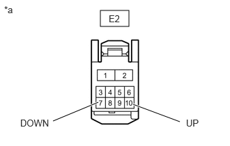
| *a | Front view of wire harness connector
(to Front Power Window Regulator Motor Assembly RH) |
Disconnect the front power window regulator motor assembly RH connector.
Procedure1
Measure the voltage according to the value(s) in the table below.
- Standard Voltage:
Tester Connection Switch Condition Specified Condition Click Location & Routing(E2)Location & Routingewd_type=routing;type=c;code=E2
Click Connector(E2)Body>Front Door Wire LH / Front Door Wire RH>Front Power Window Regulator Motor Assembly RHewd_type=component;type=c;code=E2;pinno=10,7
E2-10 (UP) - Body ground Ignition switch ON 11 to 14 V E2-7 (DOWN) - Body ground Ignition switch ON 11 to 14 V
- Result:
Proceed to OK NG
Post-procedure1
None.
OK
NG
Pre-procedure1
Disconnect the E14 multiplex network master switch assembly connector.
Disconnect the E2 front power window regulator motor assembly RH connector.
Procedure1
Measure the resistance according to the value(s) in the table below.
- Standard Resistance:
Tester Connection Condition Specified Condition Click Location & Routing(E14,E2)Location & Routingewd_type=routing;type=c,c;code=E14,E2
Click Connector(E14)Body>Front Door Wire LH / Front Door Wire RH>Multiplex Network Master Switch Assemblyewd_type=component;type=c;code=E14;pinno=20,15
Click Connector(E2)Body>Front Door Wire LH / Front Door Wire RH>Front Power Window Regulator Motor Assembly RHewd_type=component;type=c;code=E2;pinno=10,7
E14-20 (UP) - Body ground Always 10 kΩ or higher E14-15 (DOWN) - Body ground Always 10 kΩ or higher E2-10 (UP) - Body ground Always 10 kΩ or higher E2-7 (DOWN) - Body ground Always 10 kΩ or higher
- Result:
Proceed to OK NG
Post-procedure1
None.
OK
NG
Read the Data List according to the display on the GTS.
- Body Electrical > P-Door Motor > Data List
-
Tester Display Measurement Item Range Normal Condition Diagnostic Note P Door P/W Auto SW Front passenger door power window auto switch signal OFF or ON OFF: Front passenger door power window auto switch not being operated
ON: Front passenger door power window auto switch being operated-
- Body Electrical > P-Door Motor > Data List
-
Tester Display P Door P/W Auto SW - 50003 144 1
- Result:
Result Proceed to The value of P Door P/W Auto SW is OFF A None of the above conditions are met B
A
B
Read the Data List according to the display on the GTS.
- Body Electrical > P-Door Motor > Data List
-
Tester Display Measurement Item Range Normal Condition Diagnostic Note P Door P/W Up SW Front passenger door power window manual up switch signal OFF or ON OFF: Front passenger door power window manual up switch not being operated
ON: Front passenger door power window manual up switch being operated-
- Body Electrical > P-Door Motor > Data List
-
Tester Display P Door P/W Up SW - 50003 144 2
- Result:
Result Proceed to The value of P Door P/W Up SW is OFF A None of the above conditions are met B
A
B
Read the Data List according to the display on the GTS.
- Body Electrical > P-Door Motor > Data List
-
Tester Display Measurement Item Range Normal Condition Diagnostic Note P Door P/W Down SW Front passenger door power window manual down switch signal OFF or ON OFF: Front passenger door power window manual down switch not being operated
ON: Front passenger door power window manual down switch being operated-
- Body Electrical > P-Door Motor > Data List
-
Tester Display P Door P/W Down SW - 50003 144 3
- Result:
Result Proceed to The value of P Door P/W Down SW is OFF A None of the above conditions are met B
A
B
Click hereVehicle Exterior>WINDOW / GLASS>FRONT PASSENGER SIDE POWER WINDOW SWITCH>INSPECTION
- Result:
Proceed to OK NG
OK
NG
Pre-procedure1
Disconnect the E31 power window regulator switch assembly connector.
Disconnect the E20 front power window regulator motor assembly LH connector.
Procedure1
Measure the resistance according to the value(s) in the table below.
- Standard Resistance:
Tester Connection Condition Specified Condition Click Location & Routing(E31,E20)Location & Routingewd_type=routing;type=c,c;code=E31,E20
Click Connector(E31)Body>Front Door Wire LH / Front Door Wire RH>Power Window Regulator Switch Assemblyewd_type=component;type=c;code=E31;pinno=5,8,4
Click Connector(E20)Body>Front Door Wire LH / Front Door Wire RH>Front Power Window Regulator Motor Assembly LHewd_type=component;type=c;code=E20;pinno=10,4,7
E31-5 (UP) - Body ground Always 10 kΩ or higher E31-8 (AUTO) - Body ground Always 10 kΩ or higher E31-4 (DOWN) - Body ground Always 10 kΩ or higher E20-10 (UP) - Body ground Always 10 kΩ or higher E20-4 (AUTO) - Body ground Always 10 kΩ or higher E20-7 (DOWN) - Body ground Always 10 kΩ or higher
- Result:
Proceed to OK NG
Post-procedure1
None.
OK
NG
Read the Data List according to the display on the GTS.
- Body Electrical > RL-Door Motor > Data List
-
Tester Display Measurement Item Range Normal Condition Diagnostic Note RL Door P/W Auto SW Rear LH door power window auto switch signal OFF or ON OFF: Rear LH door power window auto switch not being operated
ON: Rear LH door power window auto switch being operated-
- Body Electrical > RL-Door Motor > Data List
-
Tester Display RL Door P/W Auto SW - 50003 146 1
- Result:
Result Proceed to The value of RL Door P/W Auto SW is ON A None of the above conditions are met B
A
B
Read the Data List according to the display on the GTS.
- Body Electrical > RL-Door Motor > Data List
-
Tester Display Measurement Item Range Normal Condition Diagnostic Note RL Door P/W Up SW Rear LH door power window manual up switch signal OFF or ON OFF: Rear LH door power window manual up switch not being operated
ON: Rear LH door power window manual up switch being operated-
- Body Electrical > RL-Door Motor > Data List
-
Tester Display RL Door P/W Up SW - 50003 146 2
- Result:
Result Proceed to The value of RL Door P/W Up SW is OFF A None of the above conditions are met B
A
B
Read the Data List according to the display on the GTS.
- Body Electrical > RL-Door Motor > Data List
-
Tester Display Measurement Item Range Normal Condition Diagnostic Note RL Door P/W Down SW Rear LH door power window manual down switch signal OFF or ON OFF: Rear LH door power window manual down switch not being operated
ON: Rear LH door power window manual down switch being operated-
- Body Electrical > RL-Door Motor > Data List
-
Tester Display RL Door P/W Down SW - 50003 146 3
- Result:
Result Proceed to The value of RL Door P/W Down SW is OFF A None of the above conditions are met B
A
B
Click hereVehicle Exterior>WINDOW / GLASS>POWER WINDOW SWITCH (for Rear Door)>INSPECTION
- Result:
Proceed to OK NG
OK
NG
Pre-procedure1
Disconnect the F21 rear power window regulator switch assembly LH connector.
Disconnect the F12 rear power window regulator motor assembly LH connector.
Procedure1
Measure the resistance according to the value(s) in the table below.
- Standard Resistance:
Tester Connection Condition Specified Condition Click Location & Routing(F21,F12)Location & Routingewd_type=routing;type=c,c;code=F21,F12
Click Connector(F21)Body>No. 1 Rear Door Wire / No. 2 Rear Door Wire>Rear Power Window Regulator Switch Assembly LHewd_type=component;type=c;code=F21;pinno=5,8,4
Click Connector(F12)Body>No. 1 Rear Door Wire / No. 2 Rear Door Wire>Rear Power Window Regulator Motor Assembly LHewd_type=component;type=c;code=F12;pinno=10,4,7
F21-5 (UP) - Body ground Always 10 kΩ or higher F21-8 (AUTO) - Body ground Always 10 kΩ or higher F21-4 (DOWN) - Body ground Always 10 kΩ or higher F12-10 (UP) - Body ground Always 10 kΩ or higher F12-4 (AUTO) - Body ground Always 10 kΩ or higher F12-7 (DOWN) - Body ground Always 10 kΩ or higher
- Result:
Proceed to OK NG
Post-procedure1
None.
OK
NG
Read the Data List according to the display on the GTS.
- Body Electrical > RR-Door Motor > Data List
-
Tester Display Measurement Item Range Normal Condition Diagnostic Note RR Door P/W Auto SW Rear RH door power window auto switch signal OFF or ON OFF: Rear RH door power window auto switch not being operated
ON: Rear RH door power window auto switch being operated-
- Body Electrical > RR-Door Motor > Data List
-
Tester Display RR Door P/W Auto SW - 50003 145 1
- Result:
Result Proceed to The value of RR Door P/W Auto SW is OFF A None of the above conditions are met B
A
B
Read the Data List according to the display on the GTS.
- Body Electrical > RR-Door Motor > Data List
-
Tester Display Measurement Item Range Normal Condition Diagnostic Note RR Door P/W Up SW Rear RH door power window manual up switch signal OFF or ON OFF: Rear RH door power window manual up switch not being operated
ON: Rear RH door power window manual up switch being operated-
- Body Electrical > RR-Door Motor > Data List
-
Tester Display RR Door P/W Up SW - 50003 145 2
- Result:
Result Proceed to The value of RR Door P/W Up SW is OFF A None of the above conditions are met B
A
B
Read the Data List according to the display on the GTS.
- Body Electrical > RR-Door Motor > Data List
-
Tester Display Measurement Item Range Normal Condition Diagnostic Note RR Door P/W Down SW Rear RH door power window manual down switch signal OFF or ON OFF: Rear RH door power window manual down switch not being operated
ON: Rear RH door power window manual down switch being operated-
- Body Electrical > RR-Door Motor > Data List
-
Tester Display RR Door P/W Down SW - 50003 145 3
- Result:
Result Proceed to The value of RR Door P/W Down SW is OFF A None of the above conditions are met B
A
B
Click hereVehicle Exterior>WINDOW / GLASS>POWER WINDOW SWITCH (for Rear Door)>INSPECTION
- Result:
Proceed to OK NG
OK
NG
Pre-procedure1
Disconnect the F10 rear power window regulator switch assembly RH connector.
Disconnect the F1 rear power window regulator motor assembly RH connector.
Procedure1
Measure the resistance according to the value(s) in the table below.
- Standard Resistance:
Tester Connection Condition Specified Condition Click Location & Routing(F10,F1)Location & Routingewd_type=routing;type=c,c;code=F10,F1
Click Connector(F10)Body>No. 1 Rear Door Wire / No. 2 Rear Door Wire>Rear Power Window Regulator Switch Assembly RHewd_type=component;type=c;code=F10;pinno=5,8,4
Click Connector(F1)Body>No. 1 Rear Door Wire / No. 2 Rear Door Wire>Rear Power Window Regulator Motor Assembly RHewd_type=component;type=c;code=F1;pinno=10,4,7
F10-5 (UP) - Body ground Always 10 kΩ or higher F10-8 (AUTO) - Body ground Always 10 kΩ or higher F10-4 (DOWN) - Body ground Always 10 kΩ or higher F1-10 (UP) - Body ground Always 10 kΩ or higher F1-4 (AUTO) - Body ground Always 10 kΩ or higher F1-7 (DOWN) - Body ground Always 10 kΩ or higher
- Result:
Proceed to OK NG
Post-procedure1
None.
OK
NG