HEATING / AIR CONDITIONING MAGNET VALVE(for Three-Way Valve) INSTALLATION
CAUTION / NOTICE / HINT
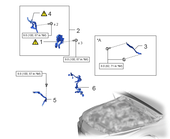
| Procedure | Part Name Code | 
|

|

|
|
|---|---|---|---|---|---|
| 1 | INSTALL HEATER ACCESSORY ASSEMBLY | 87200D | ( ) |
- | - |
| 2 | HEATER ACCESSORY ASSEMBLY WITH WATER HOSE SUB-ASSEMBLY D | - | - | - | - |
| 3 | FC CONVERTER POWER OUTLET STEERING BRACKET LH | G9A27 | - | - | - |
| 4 | CONNECT WATER HOSE SUB-ASSEMBLY D | 87209D | ()
|
- | - |
| 5 | WATER HOSE SUB-ASSEMBLY B | 87209B | - | - | - |
| 6 | STACK WIRE | 82121F | - | - | - |
| *A | for LHD | - | - |

|
N*m (kgf*cm, ft.*lbf): Specified torque | - | - |
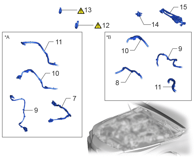
| Procedure | Part Name Code |
|
|
|
|
|---|---|---|---|---|---|
| 7 | FC CONVERTER POWER OUTLET CABLE (INVERTER WITH CONVERTER ASSEMBLY) | G9200A | - | - | - |
| 8 | FC JUNCTION CABLE | G9A2C | - | - | - |
| 9 | FC AIR COMPRESSOR MOTOR CABLE ASSEMBLY | 17A90 | - | - | - |
| 10 | FLOOR UNDER WIRE | 821H1 | - | - | - |
| 11 | NO. 1 BATTERY PACK WIRE | 821H3A | - | - | - |
| 12 | HEATER ACCESSORY ASSEMBLY | 87200D | ()
|
- | - |
| 13 | WATER HOSE | - | ()
|
- | - |
| 14 | WATER PUMP ASSEMBLY WITH MOTOR | G9040D | - | - | - |
| 15 | FRONT WIPER MOTOR AND LINK | - | - | - | - |
| *A | for LHD | *B | for RHD |
PROCEDURE

 87200D
1.INSTALL HEATER ACCESSORY ASSEMBLY
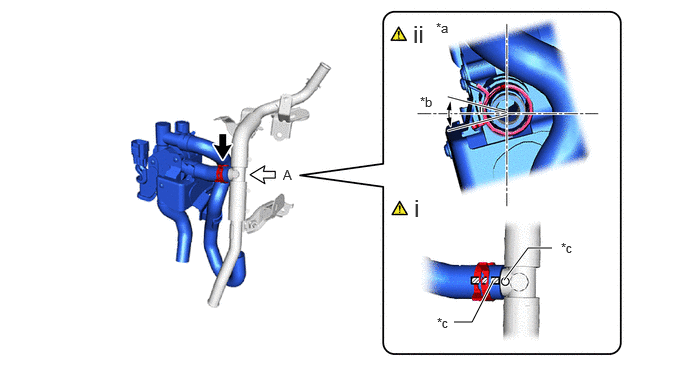
| *a | View A | *b | Hose Clip Installation Angle (30°) |
| *c | Marking (White) | - | - |
Align the positioning rib of the water hose sub-assembly D with the heater accessory assembly marking position and connect the heater accessory assembly.
- NOTICE:
-
Do not apply excessive force to the heater accessory assembly.
Make sure to install the hose clip within the range shown in the illustration.
2.INSTALL HEATER ACCESSORY ASSEMBLY WITH WATER HOSE SUB-ASSEMBLY D
- Torque:
- 9.8 N*m (100 kgf*cm, 87 in.*lbf)
G9A27
3.INSTALL FC CONVERTER POWER OUTLET STEERING BRACKET LH (for LHD)
- Torque:
- Bolt : 8.0 N*m (82 kgf*cm, 71 in.*lbf)
- Nut : 8.0 N*m (82 kgf*cm, 71 in.*lbf)
87209D
4.CONNECT WATER HOSE SUB-ASSEMBLY D
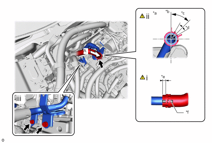
| *a | View A | *b | Vehicle Front |
| *c | Hose Clip Installation Range (45° to the Right of the Front of the Vehicle) | *d | Hose Clip Installation Angle (30°) |
| *e | Hose Clip Installation Range (3 to 7 mm (0.119 to 0.276 in.)) | *f | Marking (White) |
Connect the water hose sub-assembly D as shown in the illustration.
- NOTICE:
-
Do not apply excessive force to the water hose sub-assembly D.
Make sure to install the hose clip within the range shown in the illustration.
Install the 2 bolts.
- Torque:
- 9.8 N*m (100 kgf*cm, 87 in.*lbf)
87209B
5.CONNECT WATER HOSE SUB-ASSEMBLY B
- Torque:
- 9.8 N*m (100 kgf*cm, 87 in.*lbf)
82121F
6.CONNECT STACK WIRE
G9200A
7.CONNECT FC CONVERTER POWER OUTLET CABLE (INVERTER WITH CONVERTER ASSEMBLY) (for LHD)
G9A2C
8.CONNECT FC JUNCTION CABLE (for RHD)
17A90
9.CONNECT FC AIR COMPRESSOR MOTOR CABLE ASSEMBLY
821H1
10.CONNECT FLOOR UNDER WIRE
821H3A
11.CONNECT NO. 1 BATTERY PACK WIRE
87200D
12.CONNECT HEATER ACCESSORY ASSEMBLY
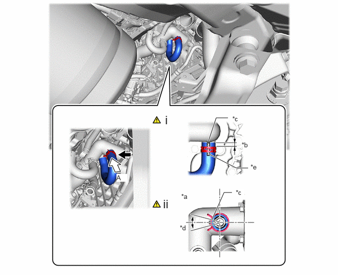
| *a | View A | *b | Hose Clip Installation Range (3 to 7 mm (0.119 to 0.276 in.)) |
| *c | Rib of the Manifold | *d | Hose Clip Installation Angle (30°) |
| *e | Marking (White) | - | - |
Connect the heater accessory assembly as shown in the illustration.
- NOTICE:
-
Do not apply excessive force to the heater accessory assembly.
Make sure to install the hose clip within the range shown in the illustration.
13.CONNECT WATER HOSE
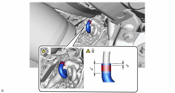
| *a | View A | *b | Hose Clip Installation Range (3 to 5 mm (0.119 to 0.196 in.)) |
Connect the water hose as shown in the illustration.
- NOTICE:
-
Do not apply excessive force to the water hose.
Make sure to install the hose clip within the range shown in the illustration.
G9040D
14.INSTALL WATER PUMP ASSEMBLY WITH MOTOR
15.INSTALL FRONT WIPER MOTOR AND LINK