HEATING / AIR CONDITIONING HEATER ASSEMBLY INSTALLATION
CAUTION / NOTICE / HINT
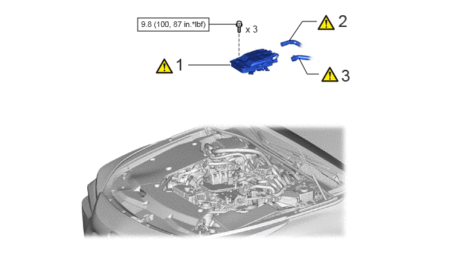
| Procedure | Part Name Code | 
|

|

|
|
|---|---|---|---|---|---|
| 1 | ELECTRIC HEATER SUB-ASSEMBLY | 87101G | ( ) |
- | - |
| 2 | WATER HOSE SUB-ASSEMBLY B | 87209B | ()
|
- | - |
| 3 | WATER HOSE SUB-ASSEMBLY C | 87209C | ()
|
- | - |

|
N*m (kgf*cm, ft.*lbf): Specified torque | - | - |
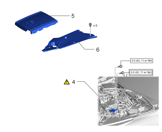
| Procedure | Part Name Code |
|
|
|
|
|---|---|---|---|---|---|
| 4 | FC CONVERTER POWER OUTLET CABLE (INVERTER WITH CONVERTER ASSEMBLY) | G9200A | ()
|
- | - |
| 5 | FC STACK COVER SUB-ASSEMBLY | 1A906 | - | - | - |
| 6 | UPPER RADIATOR SUPPORT SEAL | 53292A | - | - | - |

|
Tightening torque for "Major areas involving basic vehicle performance such as moving/turning/stopping": N*m (kgf*cm, ft.*lbf) |
|
N*m (kgf*cm, ft.*lbf): Specified torque |
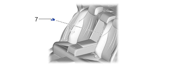
| Procedure | Part Name Code |
|
|
|
|
|---|---|---|---|---|---|
| 7 | SERVICE PLUG GRIP | G3834 | - | - | - |
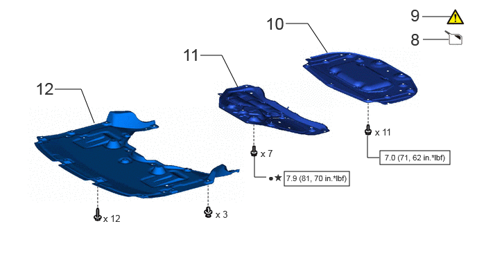
| Procedure | Part Name Code |
|
|
|
|
|---|---|---|---|---|---|
| 8 | ADD COOLANT (TOYOTA GENUINE FC STACK COOLANT (Pre-mixed)) | - | - | ()
|
- |
| 9 | INSPECT FOR COOLANT (TOYOTA GENUINE FC STACK COOLANT (Pre-mixed)) LEAK | - | ()
|
- | - |
| 10 | FRONT COMPARTMEMT UNDER COVER ASSEMBLY | 51420A | - | - | - |
| 11 | FRONT LOWER SUSPENSION MEMBER PROTECTOR | 51219 | - | - | - |
| 12 | FRONT COMPARTMENT UNDER COVER | 51441N | - | - | - |
|
|
N*m (kgf*cm, ft.*lbf): Specified torque | ● | Non-reusable part |
| ★ | Precoated part | - | - |
CAUTION / NOTICE / HINT
- HINT:
- ·
Use the same procedure for RHD and LHD vehicles.
·The procedure listed below is for LHD vehicles.
PROCEDURE

 87101G
1.INSTALL ELECTRIC HEATER SUB-ASSEMBLY
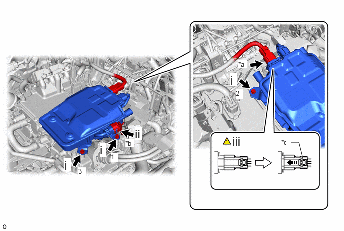
| *a | Connector (A) | *b | Connector (B) |
| *c | Green-colored Lock | - | - |

|
Slide | - | - |
Install the electric heater sub-assembly with the 3 bolts in the order shown in the illustration.
- Torque:
- 9.8 N*m (100 kgf*cm, 87 in.*lbf)
Connect the connector (B).
Remove the insulating tape from the connector (A) and then connect the connector (A) and slide the green-colored lock as shown in the illustration to securely lock it.
- CAUTION:
-
Make sure to wear insulating gloves.
- NOTICE:
-
Make sure that the connector is connected securely.
87209B
2.CONNECT WATER HOSE SUB-ASSEMBLY B
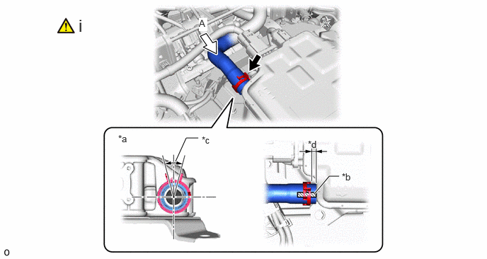
| *a | View A | *b | Marking (White) |
| *c | Hose Clip Installation Angle (30°) | *d | Hose Clip Installation Range 3 to 7 mm (0.118 to 0.276 in.)) |
Connect the water hose with its marking facing upward and install the hose sub-assembly B clip within the range shown in the illustration.
- NOTICE:
-
Do not apply excessive force to the water hose sub-assembly B.
87209C
3.CONNECT WATER HOSE SUB-ASSEMBLY C
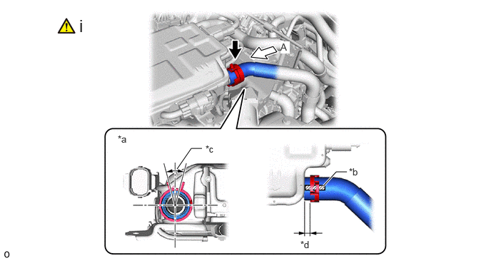
| *a | View A | *b | Marking (White) |
| *c | Hose Clip Installation Angle (30°) | *d | Hose Clip Installation Range 3 to 7 mm (0.118 to 0.276 in.)) |
Connect the water hose with its marking facing upward and install the hose sub-assembly C clip within the range shown in the illustration.
- NOTICE:
-
Do not apply excessive force to the water hose sub-assembly C.
G9200A
4.CONNECT FC CONVERTER POWER OUTLET CABLE (INVERTER WITH CONVERTER ASSEMBLY)
|
|
Click here()
|
1A906
5.INSTALL FC STACK COVER SUB-ASSEMBLY
53292A
6.INSTALL UPPER RADIATOR SUPPORT SEAL
G3834
7.INSTALL SERVICE PLUG GRIP
8.ADD COOLANT (TOYOTA GENUINE FC STACK COOLANT (Pre-mixed))
9.INSPECT FOR COOLANT (TOYOTA GENUINE FC STACK COOLANT (Pre-mixed)) LEAK
51420A
10.INSTALL FRONT COMPARTMEMT UNDER COVER ASSEMBLY
51219
11.INSTALL FRONT LOWER SUSPENSION MEMBER PROTECTOR
51441N
12.INSTALL FRONT COMPARTMENT UNDER COVER