METER / GAUGE / DISPLAY METER / GAUGE SYSTEM Malfunction in Water Temperature Warning Light
DESCRIPTION
In this circuit, the combination meter assembly receives FC Stack coolant temperature signals from the FC control ECU via the CAN communication system. The combination meter assembly displays the FC Stack coolant temperature that is calculated based on the data received from the FC control ECU.
WIRING DIAGRAM
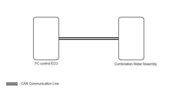
CAUTION / NOTICE / HINT
- NOTICE:
- ·
When replacing the combination meter assembly, always replace it with a new one. If a combination meter assembly which was installed to another vehicle is used, the information stored in it will not match the information from the vehicle and a DTC may be stored.
·If there is an open or short in the FC coolant temperature sensor circuit, the FC control ECU stores DTCs. Troubleshoot the FC system.
Click hereEngine / Hybrid System>FC CONTROL>FC CONTROL SYSTEM>HOW TO PROCEED WITH TROUBLESHOOTING
·Because the order of diagnosis is important to allow correct diagnosis, make sure to begin troubleshooting using How to Proceed with Troubleshooting when CAN communication system related DTCs are output.
Click herePower Source / Network>NETWORKING>CAN COMMUNICATION SYSTEM>HOW TO PROCEED WITH TROUBLESHOOTING
PROCEDURE
Check for DTCs.
- Powertrain > FC > Trouble Codes
- 50001 378
- OK:
No DTCs are output.
- Result:
Proceed to OK NG
OK
NG
Using the GTS, perform the Active Test.
Click hereVehicle Interior>METER / GAUGE / DISPLAY>METER / GAUGE SYSTEM>DATA LIST / ACTIVE TEST
- Body Electrical > Combination Meter > Active Test
-
Tester Display Measurement Item Control Range Inspection Item Coolant Hot Warning Lamp Coolant Hot Warning light OFF or ON -
- Body Electrical > Combination Meter > Active Test
-
Tester Display Coolant Hot Warning Lamp - 50004 409 57
- OK:
Value selected during Active Test is displayed.
- Result:
Proceed to OK NG
OK
NG