PARKING BRAKE ELECTRIC PARKING BRAKE SYSTEM C123A14 Supply Voltage Circuit IG Open
DESCRIPTION
| DTC No. | Detection Item | DTC Detection Condition | Trouble Area | Memory | DTC Output from | Priority | Note |
|---|---|---|---|---|---|---|---|
| C123A14 | Supply Voltage Circuit IG Open | ·
Diagnosis Condition: Ignition switch ON ·
Malfunction Status: When the EV control ECU is communicating via CAN communication, IG power is not input to the No. 2 skid control EV control ECU (brake actuator sub-assembly). ·
Detection Time: Approximately 15 seconds |
·
Wire harness and connector ·
No. 2 skid control ECU (brake actuator assembly) |
DTC stored | Brake/EPB | A | An electric parking brake system malfunction is displayed on the multi-information display. |
WIRING DIAGRAM
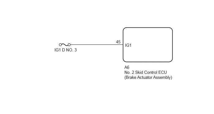
CAUTION / NOTICE / HINT
- NOTICE:
- ·
Inspect the fuses for circuits related to this system before performing the following procedure.
·To ensure that the electric parking brake does not operate, wait for 3 minutes or more with the ignition switch off, the driver door closed, and the brake pedal not depressed, then disconnect each connector, fuse and relay.
·After replacing the No. 2 skid control ECU (brake actuator assembly), perform "Calibration".
Click hereBrake>BRAKE CONTROL / DYNAMIC CONTROL SYSTEMS>ELECTRONICALLY CONTROLLED BRAKE SYSTEM>UTILITY
·After replacing the No. 2 skid control ECU (brake actuator assembly), perform "EPB Initialize" and "Acquire Tension Sensor Zero Point".
Click hereBrake>PARKING BRAKE>ELECTRIC PARKING BRAKE SYSTEM>UTILITY
PROCEDURE
Pre-procedure1
Turn the ignition switch off.
Disconnect the A6 No. 2 skid control ECU (brake actuator assembly) connector.
Turn the ignition switch to ON.
Procedure1
Measure the voltage according to the value(s) in the table below.
- Standard Voltage:
Tester Connection Condition Specified Condition Click Location & Routing(A6)Location & Routingewd_type=routing;type=c;code=A6
A6-45 (IG1) - Body ground Ignition switch ON 11 to 14 V
- Result:
Proceed to OK NG
Post-procedure1
None
OK
for LHD: Click hereBrake>BRAKE CONTROL / DYNAMIC CONTROL SYSTEMS>BRAKE ACTUATOR (for LHD)>REMOVAL
for RHD: Click hereBrake>BRAKE CONTROL / DYNAMIC CONTROL SYSTEMS>BRAKE ACTUATOR (for RHD)>REMOVAL
NG