BRAKE CONTROL / DYNAMIC CONTROL SYSTEMS BRAKE ACTUATOR(for RHD) REMOVAL
CAUTION / NOTICE / HINT
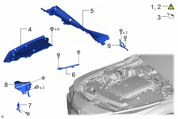
| Procedure | Part Name Code | 
|

|

|
|
|---|---|---|---|---|---|
| 1 | PRECAUTION | - | ( ) |
- | - |
| 2 | PERFORM ACCUMULATOR PRESSURE ZERO DOWN | - | ()
|
- | - |
| 3 | DRAIN BRAKE FLUID | - | - | ()
|
- |
| 4 | RADIATOR COVER PLATE | 53291B | - | - | - |
| 5 | COWL TOP VENTILATOR LOUVER SUB-ASSEMBLY | 55708 | - | - | - |
| 6 | FENDER APRON BRACE SUB-ASSEMBLY RH | 53705F | - | - | - |
| 7 | FC JUNCTION CABLE BRACKET | - | - | - | - |
| 8 | RELAY BLOCK | - | - | - | - |
| 9 | WIRE HARNESS CLAMP BRACKET | - | - | - | - |
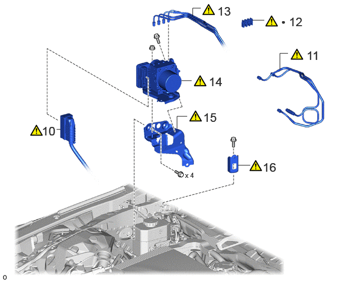
| Procedure | Part Name Code |
|
|
|
|
|---|---|---|---|---|---|
| 10 | FRONT COMPARTMENT MAIN WIRE | 82111C | ()
|
- | - |
| 11 | REMOVE BRAKE TUBE | - | ()
|
- | - |
| 12 | BRAKE TUBE CLAMP | - | ()
|
- | - |
| 13 | DISCONNECT BRAKE TUBE | - | ()
|
- | - |
| 14 | BRAKE ACTUATOR WITH BRACKET | - | ()
|
- | - |
| 15 | NO. 5 BRAKE ACTUATOR BRACKET | 44595 | ()
|
- | - |
| 16 | NO. 3 BRAKE ACTUATOR BRACKET | 44593 | ()
|
- | - |
| ● | Non-reusable part | - | - |
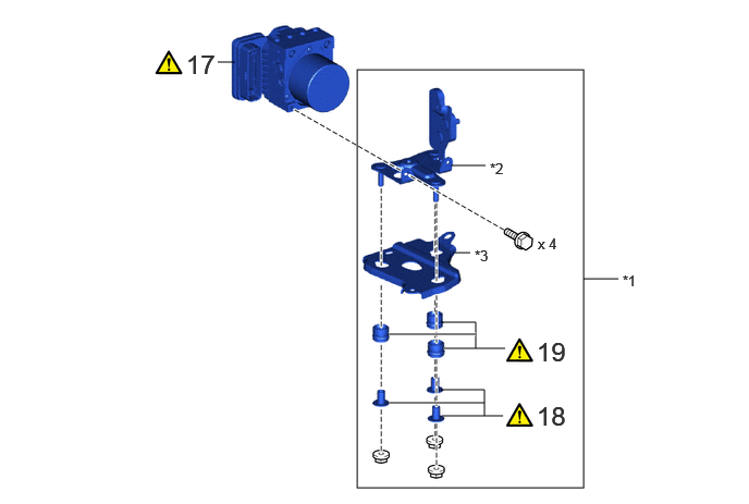
| Procedure | Part Name Code |
|
|
|
|
|---|---|---|---|---|---|
| 17 | BRAKE ACTUATOR ASSEMBLY | 44510 | ()
|
- | - |
| 18 | NO. 1 BRAKE ACTUATOR CASE COLLAR | 44521A | ()
|
- | - |
| 19 | BRAKE ACTUATOR BRACKET CUSHION | 44547B | ()
|
- | - |
| *1 | BRAKE ACTUATOR BRACKET ASSEMBLY | *2 | NO. 1 BRAKE ACTUATOR BRACKET |
| *3 | NO. 2 BRAKE ACTUATOR BRACKET | - | - |
CAUTION / NOTICE / HINT
The necessary procedures (adjustment, calibration, initialization or registration) that must be performed after parts are removed and installed, or replaced during brake actuator assembly removal/installation are shown below.
| Replaced Part or Performed Procedure | Necessary Procedure | Effect/Inoperative Function when Necessary Procedure not Performed | Link |
|---|---|---|---|
| Disconnect cable from negative (-) auxiliary battery terminal | Memorize steering angle neutral point | Parking assist monitor system | ()
|
| Panoramic view monitor system | ()
|
||
| No. 2 skid control ECU (brake actuator assembly) | Update ECU security key | Vehicle control history (RoB) are stored | ()
|
1.
Bleed air 2.
Perform "Calibration" |
·
DTCs are stored ·
ABS warning light illuminates ·
Brake system warning light (yellow indicator) illuminates ·
Slip indicator light illuminates ·
Electronically controlled brake system disabled or malfunctions |
()
|
|
·
Perform "EPB Initalize" ·
Acquire tension sensor zero point |
Electric parking brake system | ()
|
- HINT:
-
When the cable is disconnected/reconnected to the auxiliary battery terminal, systems temporarily stop operating. However, each system has a function that completes learning the first time the system is used.
- ·
Learning completes when vehicle is driven
Effect/Inoperative Function When Necessary Procedures are not Performed Necessary Procedures Link Lane tracing assist system Drive the vehicle straight ahead at 35 km/h (22 mph) or more for 5 seconds or more. ( )
Pre-collision system Adaptive high beam system
·Learning completes when vehicle is operated normally
Effect/Inoperative Function When Necessary Procedures are not Performed Necessary Procedures Link Air conditioning system After the ignition switch is turned to ON, theservo motor and expansion valve standardposition is recognized. -
CAUTION / NOTICE / HINT
- NOTICE:
-
While the auxiliary battery is connected, even if the ignition switch is off, the brake control system activates when the brake pedal is depressed or any door courtesy switch turns on. Therefore, when servicing the brake system components, do not operate the brake pedal or open/close the doors while the auxiliary battery is connected.
PROCEDURE

 1. PRECAUTION
|
|
|
2.PERFORM ACCUMULATOR PRESSURE ZERO DOWN
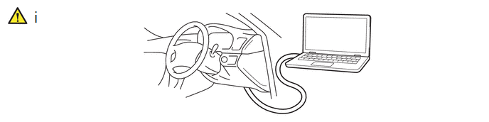
Using the GTS, perform the accumulator pressure zero down operation.
1. Select "Motor Deactivate" on the "ECB Utility" screen.
- Chassis > Brake/EPB > Utility
-
Tester Display ECB Utility - 50005 435 2617
2. Perform "Motor Deactivate" according to the display on the GTS.
3. Select "ECB Deactivate" on the "ECB Utility" screen.
- Chassis > Brake/EPB > Utility
-
Tester Display ECB Utility - 50005 435 3617
4. Perform "ECB Deactivate" according to the display on the GTS.
5. Depress the brake pedal 40 times or more to return all the fluid in the accumulator back to the reservoir.
- HINT:
-
A buzzer may sound due to low accumulator pressure. As this is not a malfunction, continue the procedure.
6. Check that the brake pedal is firm.
- NOTICE:
-
If the brake pedal is not firm or the pump motor continues to operate even after depressing the brake pedal 40 times or more, the accumulator pressure zero down operation is not complete.
7. Disconnect the cable from the negative (-) auxiliary battery terminal.
Click hereGeneral>MAINTENANCE>AUXILIARY BATTERY>REMOVAL
- CAUTION:
-
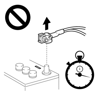
- ·
Wait at least 60 seconds after disconnecting the cable from the negative (-) auxiliary battery terminal to disable the SRS system.
·If the airbag deploys for any reason, it may cause a serious accident.
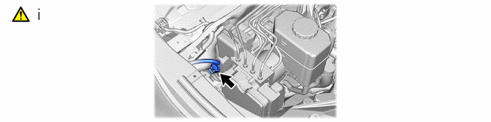
When the accumulator pressure zero down could not be performed using the GTS.
- NOTICE:
-
If DTCs are output, the accumulator pressure zero down operation may not be complete. In this case, perform the following procedure.
1. Remove the cowl top ventilator louver sub-assembly.
Click hereVehicle Exterior>WIPER / WASHER>FRONT WIPER MOTOR>REMOVAL
2. With the ignition switch off, disconnect the brake master cylinder with pump assembly connector.
- NOTICE:
-
Be careful not to allow any brake fluid to enter the connector.
3. Depress the brake pedal 40 times or more to return all the fluid in the accumulator back to the reservoir.
4. Check that the brake pedal is firm.
- NOTICE:
-
If the brake pedal is not firm or the pump motor continues to operate even after depressing the brake pedal 40 times or more, the accumulator pressure zero down operation is not complete.
5. Disconnect the cable from the negative (-) auxiliary battery terminal.
Click hereGeneral>MAINTENANCE>AUXILIARY BATTERY>REMOVAL
- CAUTION:
-
- ·
Wait at least 60 seconds after disconnecting the cable from the negative (-) auxiliary battery terminal to disable the SRS system.
·If the airbag deploys for any reason, it may cause a serious accident.
3.DRAIN BRAKE FLUID
|
|
|
53291B
4.REMOVE RADIATOR COVER PLATE
55708
5.REMOVE COWL TOP VENTILATOR LOUVER SUB-ASSEMBLY
53705F
6.REMOVE FENDER APRON BRACE SUB-ASSEMBLY RH

7.REMOVE FC JUNCTION CABLE BRACKET
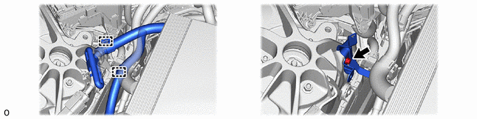
8.DISCONNECT RELAY BLOCK

9.REMOVE WIRE HARNESS CLAMP BRACKET

82111C
10.DISCONNECT FRONT COMPARTMENT MAIN WIRE
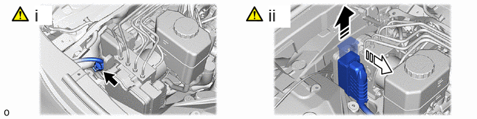

|
Release the lock lever | 
|
Disconnect the connector |
Disconnect the brake master cylinder with pump assembly connector.
- NOTICE:
-
Be careful not to allow any brake fluid to enter the connector.
Release the lock lever and disconnect the connector from the brake actuator assembly.
- NOTICE:
-
Be careful not to allow any brake fluid to enter the connector.
11.REMOVE BRAKE TUBE
|
|
|
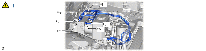
| *a | From 1st Chamber of Brake Booster with Master Cylinder Assembly | *b | From 2nd Chamber of Brake Booster with Master Cylinder Assembly |
| *c | To Front Wheel Cylinder Assembly RH | *d | To Front Wheel Cylinder Assembly LH |
| *e | To Rear Wheel Cylinder Assembly RH | *f | To Rear Wheel Cylinder Assembly LH |
Use tags or make a memo to identify the places to reconnect the brake tubes.
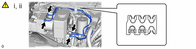
Using a union nut wrench, disconnect the 2 brake tubes from the brake actuator assembly and brake booster with master cylinder assembly.
Disengage the 2 clamps and remove the 2 brake tubes from the brake tube clamp.
12.REMOVE BRAKE TUBE CLAMP
|
|
|
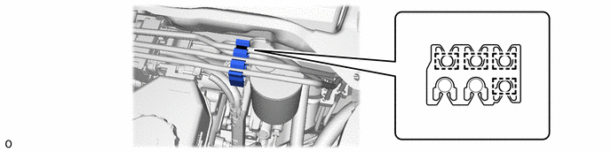
13.DISCONNECT BRAKE TUBE
|
|
|
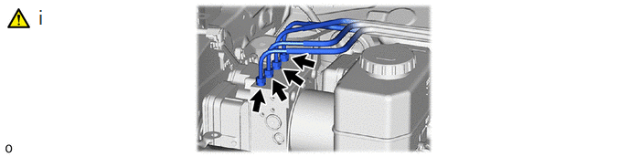
Using a union nut wrench, disconnect the 4 brake tubes from the brake actuator assembly.
14.REMOVE BRAKE ACTUATOR WITH BRACKET
|
|
|

44595
15.REMOVE NO. 5 BRAKE ACTUATOR BRACKET
|
|
|

44593
16.REMOVE NO. 3 BRAKE ACTUATOR BRACKET
|
|
|

44510
17.REMOVE BRAKE ACTUATOR ASSEMBLY
|
|
|
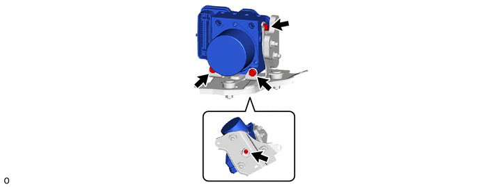
44521A
18.REMOVE NO. 1 BRAKE ACTUATOR CASE COLLAR
|
|
|
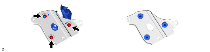
44547B
19.REMOVE BRAKE ACTUATOR BRACKET CUSHION
|
|
|