HYBRID / BATTERY CONTROL HYBRID CONTROL SYSTEM Pattern Select Switch Snow Mode Circuit
DESCRIPTION
When the SNOW mode switch (pattern select switch assembly) is operated, the SNOW mode signal is sent to the EV control ECU, and drive torque is controlled so that operability is improved in response to operation of the accelerator pedal by the driver when driving on slippery roads, etc.
WIRING DIAGRAM
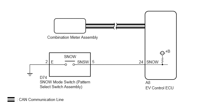
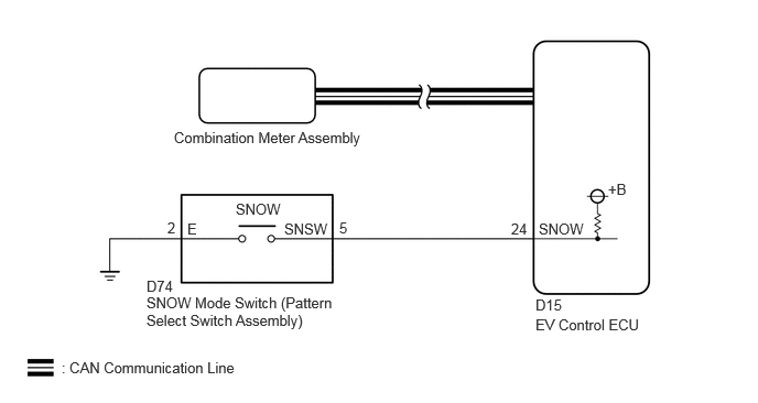
PROCEDURE
- Result:
Result Proceed to All of the ECUs and sensors that are currently connected to the CAN communication system are displayed A None of the ECUs and sensors that are currently connected to the CAN communication system are displayed, or some of them are not displayed B
A
B
Click herePower Source / Network>NETWORKING>CAN COMMUNICATION SYSTEM>HOW TO PROCEED WITH TROUBLESHOOTING
Enter the following menus: System Select / Health Check.
Check for DTCs.
- Result:
Result Proceed to No DTCs are output. A DTCs are output. B
Turn the ignition switch off.
A
B
Read the value displayed on the GTS.
- Powertrain > EV > Data List
-
Tester Display Snow Mode Switch - 50003 397 507
- Powertrain > EV > Data List
-
Tester Display Measurement Item Range Normal Condition Snow Mode Switch SNOW mode switch (pattern select switch assembly) condition ON or OFF SNOW mode switch (pattern select switch assembly) not operated: OFF
SNOW mode switch (pattern select switch assembly) being pushed and held: ON
- Result:
Result Proceed to The display changes according to the SNOW mode switch (pattern select switch assembly) operation. A The display does not change according to the SNOW mode switch (pattern select switch assembly) operation. B
Turn the ignition switch off.
A
Click hereEngine / Hybrid System>HYBRID / BATTERY CONTROL>HYBRID CONTROL SYSTEM>PROBLEM SYMPTOMS TABLE
B
Click hereDrivetrain>Q710 (HYBRID TRANSMISSION / TRANSAXLE)>PATTERN SELECT SWITCH>INSPECTION
- Result:
Proceed to OK NG
OK
NG
Disconnect the D74 SNOW mode switch (pattern select switch assembly) connector.
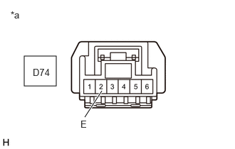
| *a | Front view of wire harness connector
(to SNOW Mode Switch (Pattern Select Switch Assembly)) |
Measure the resistance according to the value(s) in the table below.
- Standard Resistance:
Tester Connection Condition Specified Condition Click Location & Routing(D74)Location & Routingewd_type=routing;type=c;code=D74
Click Connector(D74)Instrument Panel>Instrument Panel Wire>Pattern Select Switch Assemblyewd_type=component;type=c;code=D74;pinno=2
D74-2 (E) - Body ground Ignition switch off Below 1 Ω
- Result:
Proceed to OK NG
Reconnect the D74 SNOW mode switch (pattern select switch assembly) connector.
OK
NG
Disconnect the D74 SNOW mode switch (pattern select switch assembly) connector.
Disconnect the A8*1 or D15*2 EV control ECU connector.
*1: for LHD
*2: for RHD
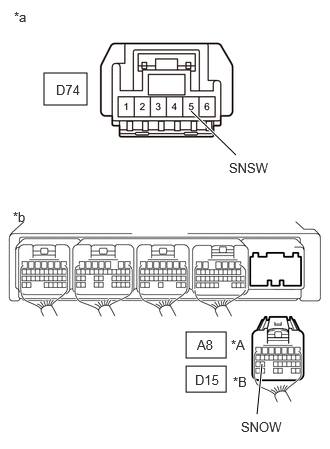
| *A | for LHD |
| *B | for RHD |
| *a | Front view of wire harness connector
(to SNOW Mode Switch (Pattern Select Switch Assembly)) |
| *b | Rear view of wire harness connector
(to EV Control ECU) |
Measure the resistance according to the value(s) in the table below.
- Standard Resistance:
for LHD: Tester Connection Condition Specified Condition Click Location & Routing(D74,A8)Location & Routingewd_type=routing;type=c,c;code=D74,A8
Click Connector(D74)Instrument Panel>Instrument Panel Wire>Pattern Select Switch Assemblyewd_type=component;type=c;code=D74;pinno=5
Click Connector(A8)Instrument Panel>Front Compartment Main Wire>EV Control ECUewd_type=component;type=c;code=A8;pinno=24
D74-5 (SNSW) - A8-24 (SNOW) Ignition switch off Below 1 Ω D74-5 (SNSW) or A8-24 (SNOW) - Body ground Ignition switch off 10 kΩ or higher
for RHD: Tester Connection Condition Specified Condition Click Location & Routing(D74,D15)Location & Routingewd_type=routing;type=c,c;code=D74,D15
Click Connector(D74)Instrument Panel>Instrument Panel Wire>Pattern Select Switch Assemblyewd_type=component;type=c;code=D74;pinno=5
Click Connector(D15)Instrument Panel>Instrument Panel Wire>EV Control ECUewd_type=component;type=c;code=D15;pinno=24
D74-5 (SNSW) - D15-24 (SNOW) Ignition switch off Below 1 Ω D74-5 (SNSW) or D15-24 (SNOW) - Body ground Ignition switch off 10 kΩ or higher
- Result:
Proceed to OK NG
Reconnect the A8*1 or D15*2 EV control ECU connector.
*1: for LHD
*2: for RHD
Reconnect the D74 SNOW mode switch (pattern select switch assembly) connector.
OK
NG