Home › Engine / Hybrid System › FUEL › HYDROGEN TANK ASSEMBLY (for No. 1)
RM37H0E _51 Engine / Hybrid System _097300 FUEL _0465032 HYDROGEN TANK ASSEMBLY(for No. 1) A

FUEL  HYDROGEN TANK ASSEMBLY(for No. 1)  INSTALLATION  


CAUTION / NOTICE / HINT
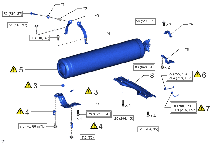
COMPONENTS (INSTALLATION)
A481961N01
5.656,0.833 6.135,0.833 false 5.198,0.927 5.542,1.458 5.542,1.458 5.708,1.458 false 5.396,0.875 5.563,0.313 5.563,0.313 5.729,0.313 false 1.479,2.594 1.042,2.26 1.042,2.26 0.875,2.26 false 1.729,2.813 1.135,2.958 1.135,2.958 0.969,2.958 false 6.188,1.302 6.531,1.583 0.344,0.281 18 false 2 6.156,0.74 6.521,0.896 0.365,0.156 10 false ● *2 5.76,0.219 6.156,0.385 0.396,0.167 10 false ● *1 6.01,1.344 6.167,1.542 0.156,0.198 10 false ● 0.74,2.813 1.083,3.094 0.344,0.281 18 false 1 0.563,2.865 0.719,3.063 0.156,0.198 10 false ● 0.51,2.167 0.875,2.323 0.365,0.156 10 false ● *2

Procedure Part Name Code
Z101186

Z101188

Z101187

1 NO. 1 HYDROGEN TANK INFORMATION LABEL 77A18 (Click here) - -
2 HYDROGEN TANK PRESSURE INFORMATION LABEL 77A61 (Click here) - -

*1 TAPE *2 LABEL COVER FILM
● Non-reusable part - -

A479292N02
5.729,3.438 6.573,3.76 0.844,0.323 4.479,2.167 5.156,2.344 0.677,0.177 0.625,4.135 1.573,4.323 0.948,0.188 0.083,0.365 0.76,0.552 0.677,0.188 3.781,3.875 4.479,4.052 0.698,0.177 5.698,3.406 6.594,3.792 0.896,0.385 4.458,2.135 5.188,2.365 0.729,0.229 2.677,4.5 3.177,4.677 0.5,0.177 0.26,0.75 0.938,0.938 0.677,0.188 0.99,1.177 1.667,1.365 0.677,0.188 4.531,0.625 5.208,0.813 0.677,0.188 2.875,3.708 3.729,3.938 0.854,0.229 2.896,3.74 3.698,3.906 0.802,0.167 4.615,4.24 5.313,4.417 0.698,0.177 5.563,2.344 6.469,2.729 0.906,0.385 5.594,2.375 6.438,2.698 0.844,0.323 4.49,2.792 4.813,2.521 4.813,2.521 4.979,2.521 false 2.427,3.052 2.802,3.052 false 2.656,3.479 3.156,3.479 false 1.333,2.865 2.052,2.865 false 2.417,4.188 3,4.188 false 1.042,3.74 1.771,3.74 false 5.583,1.979 6,1.646 6,1.646 6.167,1.646 false 5.719,1.146 6.135,0.813 6.135,0.813 6.302,0.813 false 2.865,1.104 3.531,1.104 false 2.396,0.698 2.896,0.531 2.896,0.531 3.146,0.531 false 2.01,0.615 2.583,0.292 2.583,0.292 2.75,0.292 false 1.604,0.542 1.844,0.156 1.844,0.156 2.01,0.156 false 0.833,2.333 1.917,2.333 false 5.208,0.74 5.458,0.74 false 5.167,2.25 5.417,2.25 false 1.573,4.24 1.823,4.24 false 2.646,3.833 2.896,3.833 false 1.667,1.26 1.917,1.26 false 0.938,0.865 1.188,0.865 false 0.76,0.458 1.01,0.458 false 4.115,3.875 4.115,3.542 false 4.958,4.24 4.958,3.906 false 2.427,4.594 2.677,4.594 false 5.75,3.115 5.51,3.604 5.51,3.604 5.729,3.604 false 5.583,2.531 5.406,2.531 5.406,2.531 5.521,2.927 false 5.552,0.75 5.813,0.896 0.26,0.146 10 false x 2 4.198,3.438 4.458,3.583 0.26,0.146 10 false x 4 5.031,3.792 5.292,3.938 0.26,0.146 10 false x 4 5.021,2.375 5.354,2.635 0.333,0.26 18 false 8 6.896,3.49 7.146,3.75 0.25,0.26 18 false 7 6.771,2.365 7.104,2.625 0.333,0.26 18 false 6 0.635,2.188 0.813,2.427 0.177,0.24 18 false 5 2.042,0.073 2.271,0.229 0.229,0.156 10 false *1 3.188,0.448 3.458,0.594 0.271,0.146 10 false *3 3.563,1.031 3.771,1.177 0.208,0.146 10 false *4 6.344,0.74 6.594,0.875 0.25,0.135 10 false *5 6.198,1.573 6.469,1.719 0.271,0.146 10 false *6 3.198,3.406 3.469,3.563 0.271,0.156 10 false *7 0.844,3.604 1.052,3.854 0.208,0.25 18 false 4 1.115,2.719 1.313,2.99 0.198,0.271 18 false 3 3.302,4.083 3.51,4.344 0.208,0.26 18 false 4 3.146,2.938 3.333,3.198 0.188,0.26 18 false 3 2.792,0.208 3.021,0.375 0.229,0.167 10 false *2 0.656,4.156 1.604,4.344 0.948,0.188 8 false 7.5 (76, 66 in.*lbf) 4.521,2.177 5.188,2.333 0.667,0.156 8 false 83 (846, 61) 0.125,0.385 0.802,0.563 0.677,0.177 8 false 50 (510, 37) 3.833,3.896 4.5,4.063 0.667,0.167 8 false 20 (204, 15) 5.771,3.469 6.438,3.615 0.667,0.146 8 false 25 (255, 18) 5.771,3.604 6.583,3.75 0.813,0.146 8 false 21.4 (218, 16)* 5.51,2.167 5.771,2.313 0.26,0.146 10 false x 2 2.563,3.875 2.823,4.021 0.26,0.146 10 false x 4 2.74,4.531 3.229,4.677 0.49,0.146 8 false 7.5 (76) 0.292,0.771 0.969,0.948 0.677,0.177 8 false 50 (510, 37) 1.021,1.198 1.698,1.375 0.677,0.177 8 false 50 (510, 37) 4.552,0.635 5.229,0.813 0.677,0.177 8 false 50 (510, 37) 2.948,3.75 3.729,3.906 0.781,0.156 8 false 73.8 (753, 54) 4.677,4.25 5.344,4.417 0.667,0.167 8 false 20 (204, 15) 5.635,2.406 6.302,2.552 0.667,0.146 8 false 25 (255, 18) 5.635,2.542 6.448,2.688 0.813,0.146 8 false 21.4 (218, 16)*

Procedure Part Name Code
Z101186

Z101188

Z101187

3 NO. 1 HYDROGEN TANK FRAME SEAT 77B61B (Click here) - -
4 NO. 2 FLOOR UNDER COVER BRACKET 51425C (Click here) - -
5 NO. 1 HYDROGEN TANK ASSEMBLY 77A10 (Click here) - -
6 NO. 5 HYDROGEN TANK TUBE 77BA5 (Click here) - -
7 NO. 2 HYDROGEN TANK TUBE 77BA2 (Click here) - -
8 FRONT FLOOR BRACE SUB-ASSEMBLY CENTER 57501C - - -

*1 FRONT HYDROGEN TANK SPRING BOLT CAP *2 COMPRESSION SPRING
*3 NO. 1 HYDROGEN TANK BAND SUB-ASSEMBLY RH *4 NO. 1 HYDROGEN TANK BAND SUB-ASSEMBLY LH
*5 UPPER HYDROGEN TANK BRACKET *6 LOWER HYDROGEN TANK BRACKET
*7 NO. 1 HYDROGEN TANK FRAME SUB-ASSEMBLY - -
V111893

Tightening torque for "Major areas involving basic vehicle performance such as moving/turning/stopping" : N*m (kgf*cm, ft.*lbf)
V100146

N*m (kgf*cm, ft.*lbf): Specified torque
* For use with union nut wrench - -

A479191N07
3.219,1.969 4.24,2.323 1.021,0.354 3.188,1.938 4.271,2.354 1.083,0.417 2.615,2.135 3.042,2.646 3.042,2.646 3.271,2.646 false 2.885,2.094 3.083,2.167 3.083,2.167 3.219,2.167 false 3.188,2.375 3.438,2.531 0.25,0.156 10 false *1 3.479,2.563 3.76,2.708 0.281,0.146 10 false *2 3.313,2.542 3.469,2.74 0.156,0.198 10 false ● 3.26,2 4.292,2.156 1.031,0.156 8 false 9.0 (92, 80 in.*lbf) 3.26,2.167 4.271,2.313 1.01,0.146 8 false 7.2 (73, 64 in.*lbf)*

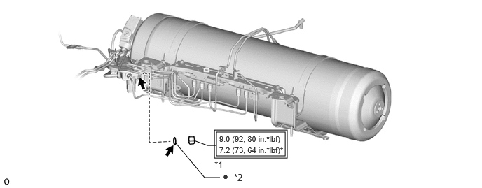
*1 NO. 1 HYDROGEN SUPPLY REGULATOR PLUG *2 O-RING
V111893

Tightening torque for "Major areas involving basic vehicle performance such as moving/turning/stopping" : N*m (kgf*cm, ft.*lbf) * For use with SST
● Non-reusable part
V100135

TOYOTA Genuine FC Grease

A482143N04
5.854,2.396 6.854,2.594 1,0.198 4.865,3.51 5.833,3.708 0.969,0.198 6.719,3.344 6.552,3.344 6.552,3.344 6.302,2.927 false 1.125,2.229 1.323,1.865 1.323,1.865 1.49,1.865 false 2.531,1.646 2.76,0.948 2.76,0.948 2.927,0.948 false 4.135,1.177 4.302,1.177 4.302,1.177 4.635,1.677 false 4.906,0.708 5.073,0.708 5.073,0.708 5.604,1.042 false 6.531,0.604 6.781,0.604 false 4.385,3.115 4.219,3.115 4.219,3.115 3.938,2.688 false 5.833,3.615 6.083,3.615 6.083,3.615 6.083,3.531 false 5.604,3.031 5.656,2.51 5.656,2.51 5.844,2.51 false 6.51,0.24 6.781,0.24 false 1.333,0.906 1.5,0.438 1.5,0.438 1.667,0.438 false 0.625,3.052 0.854,3.219 0.229,0.167 10 false x 3 1.063,2.906 1.292,3.073 0.229,0.167 10 false x 6 1.25,2.75 1.479,2.917 0.229,0.167 10 false x 4 2.51,2.365 2.74,2.531 0.229,0.167 10 false x 8 2.802,2.104 3.031,2.271 0.229,0.167 10 false x 2 3.021,3.135 3.25,3.302 0.229,0.167 10 false x 8 3.635,3.104 3.865,3.271 0.229,0.167 10 false x 3 4.76,2.292 4.99,2.458 0.229,0.167 10 false x 7 5.104,2.219 5.333,2.385 0.229,0.167 10 false x 2 6.094,1.75 6.323,1.917 0.229,0.167 10 false x 2 6.396,1.969 6.625,2.135 0.229,0.167 10 false x 6 6.615,1.51 6.844,1.677 0.229,0.167 10 false x 4 6.156,3.396 6.385,3.563 0.229,0.167 10 false x 2 6.344,0.448 6.542,0.698 0.198,0.25 18 false 9 1.521,1.708 1.865,1.969 0.344,0.26 18 false 19 2.969,0.802 3.344,1.073 0.375,0.271 18 false 18 4.729,2.969 5.073,3.219 0.344,0.25 18 false 17 3.844,1.031 4.177,1.292 0.333,0.26 18 false 15 4.594,0.563 4.906,0.813 0.313,0.25 18 false 14 6.75,3.188 7.104,3.458 0.354,0.271 18 false 11 4.906,3.531 5.865,3.688 0.958,0.156 8 false 7.5 (76, 66 in.*lbf) 5.896,2.427 6.854,2.583 0.958,0.156 8 false 5.0 (51, 44 in.*lbf) 5.865,2.615 6.104,2.792 0.24,0.177 10 false *1 5.365,0.083 6.542,0.365 1.177,0.281 18 false 10, 12, 13 0.958,1.469 1.188,1.635 0.229,0.167 10 false x 8 1.583,1.51 1.813,1.677 0.229,0.167 10 false x 3 2.021,0.292 2.396,0.563 0.375,0.271 18 false 16

Procedure Part Name Code
Z101186

Z101188

Z101187

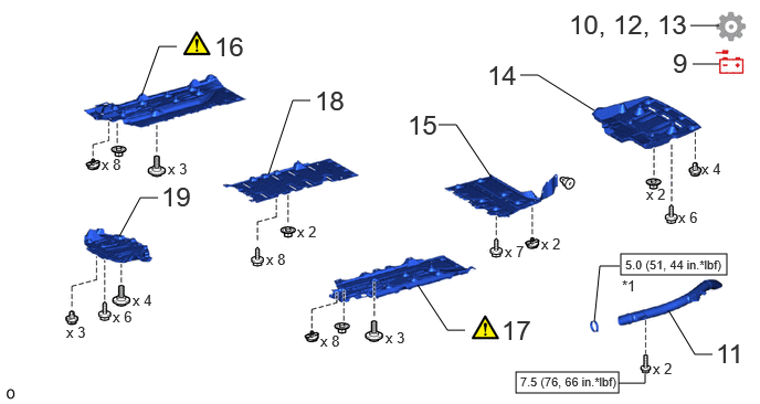
9 CABLE TO NEGATIVE AUXILIARY BATTERY TERMINAL - - - -
10 FIRST LEAK CHECK - - - (Click here)
11 NO. 3 FC EXHAUST PIPE 17DB3 - - -
12 INITIALIZATION AFTER RECONNECTING BATTERY TERMINAL - - - (Click here)
13 SECOND LEAK CHECK - - - (Click here)
14 NO. 1 FLOOR UNDER COVER 58398F - - -
15 REAR FLOOR SIDE MEMBER COVER LH 57628E - - -
16 NO. 1 FLOOR BOARD SUB-ASSEMBLY 58401M (Click here) - -
17 NO. 2 FLOOR BOARD SUB-ASSEMBLY 58402K (Click here) - -
18 REAR NO. 3 FLOOR BOARD SUB-ASSEMBLY 58403L - - -
19 REAR NO. 4 FLOOR BOARD SUB-ASSEMBLY 58404B - - -

*1 HOSE CLAMP - -
V100146

N*m (kgf*cm, ft.*lbf): Specified torque - -

PROCEDURE

Hide 77A18 1.INSTALL NO. 1 HYDROGEN TANK INFORMATION LABEL

Z101186

HINT:

This procedure is only performed when the No. 1 hydrogen tank information label is being replaced.


a.
A482137C01
4.042,0.969 4.281,0.344 4.281,0.344 4.479,0.344 true 4.51,0.271 4.823,0.427 0.313,0.156 10 false *1 0.573,0.135 0.99,0.406 0.417,0.271 18 false i, ii 5.198,1.01 5.51,1.167 0.313,0.156 10 false *a 3.063,1.417 3.375,1.573 0.313,0.156 10 false *b
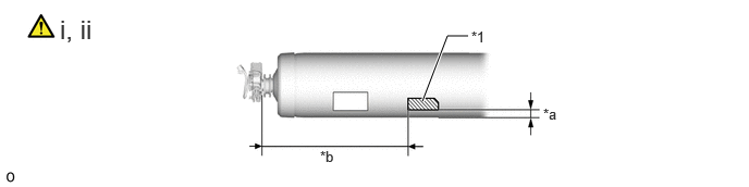
*1 No. 1 Hydrogen Tank Information Label - -
*a 37 mm (1.46 in.) *b 670 to 690 mm (26.4 to 27.1 in.)


i.

Apply the No. 1 hydrogen tank information label to the No. 1 hydrogen tank assembly as shown in the illustration.

NOTICE:

Avoid the air bubbles as much as possible.


ii.

Apply new label cover film over the No. 1 hydrogen tank information label.

NOTICE:
·

Do not protrude from the frame of the label.

·

Avoid the air bubbles as much as possible.


Hide 77A61 2.REPLACE HYDROGEN TANK PRESSURE INFORMATION LABEL

Z101186

HINT:

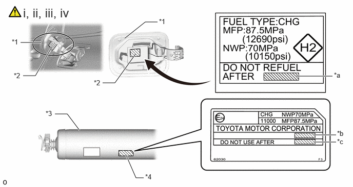
This procedure is for when the No. 1 hydrogen tank assembly is replaced, and the contents of the labels applied to the fuel filler opening lid assembly is changed.


a.
A479228C01
6,1.552 6.75,1.552 true 6.365,2.75 6.823,2.75 true 6.365,2.896 6.823,2.896 true 0.417,0.865 0.833,0.865 true 2.531,0.781 2.948,0.448 2.948,0.448 3.198,0.448 true 2.083,1.688 2.333,1.688 2.333,1.688 2.75,1.104 true 0.469,1.542 0.719,1.542 0.719,1.542 1.052,0.958 true 1.115,2.323 1.365,2.323 1.365,2.323 1.615,2.656 true 2.552,3.146 2.76,3.625 2.76,3.625 2.917,3.625 true 6.781,1.448 7.021,1.635 0.24,0.188 10 false *a 6.844,2.635 7.083,2.823 0.24,0.188 10 false *b 6.844,2.802 7.083,2.99 0.24,0.188 10 false *c 3.229,0.354 3.458,0.521 0.229,0.167 10 false *1 0.24,0.771 0.469,0.938 0.229,0.167 10 false *1 1.906,1.604 2.135,1.771 0.229,0.167 10 false *2 0.281,1.458 0.51,1.625 0.229,0.167 10 false *2 0.927,2.229 1.156,2.396 0.229,0.167 10 false *3 0.469,0.115 1.573,0.375 1.104,0.26 18 false i, ii, iii, iv 2.948,3.521 3.177,3.688 0.229,0.167 10 false *4
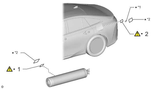
*1 Fuel Filler Opening Lid Assembly *2 Hydrogen Tank Pressure Information Label
*3 No. 1 Hydrogen Tank Assembly *4 Hydrogen Tank Information Label
*a Tape with DO NOT USE AFTER date recorded *b Location to record Tank Inspection Passed date
*c Location to record DO NOT USE AFTER date - -


i.

Peel off the label cover film applied over the hydrogen tank pressure information label.

NOTICE:

When peeling off the label cover film, if the hydrogen tank pressure information label is also peeled off, replace it with a new hydrogen tank pressure information label.


ii.

Record the item onto new tape.

Recorded Item Recorded Contents
DO NOT USE AFTER date Check the DO NOT USE AFTER dates on the hydrogen tank information labels of the 3 hydrogen tank assemblies in the vehicle and record the oldest date (year/month).
HINT:

From the 3 hydrogen tank assemblies installed to the vehicle, use the Tank Inspection Passed date of whichever tank has an older date, and starting from a point 1 month before the Tank Inspection Passed date, record a month/year that is 15 years in the future.

Example:

If the Tank Inspection Passed dates of each hydrogen tank assembly are as follows:

No. 1 Hydrogen Tank Assembly: 2020.2, No. 2 Hydrogen Tank Assembly: 2020.3, No. 3 Hydrogen Tank Assembly: 2020.4

The No. 1 Hydrogen Tank Assembly has an older date, so DO NOT USE AFTER date record the date as 2035.1.


NOTICE:
·

Do not protrude from the frame of the label.

·

When writing the text by hand, be sure to write the letters and numbers clearly and distinctly so that there can be no confusion.


HINT:

When recording the items with the label printer, use black lettering on transparent tape.

Font Size
Gothic 3.0 mm (0.118 in.)


iii.

Apply the tape with item recorded to the hydrogen tank pressure information label.


iv.

Apply new label cover film over the hydrogen tank pressure information label.

NOTICE:

When applying the tape, avoid air bubbles as much as possible.


Hide 77B61B 3.INSTALL NO. 1 HYDROGEN TANK FRAME SEAT

Z101186

HINT:

This procedure is only performed when the No. 1 hydrogen tank frame seat is being replaced with a new one.


Hide 51425C 4.INSTALL NO. 2 FLOOR UNDER COVER BRACKET

Z101186

HINT:

This procedure is only performed when the No. 2 floor under cover bracket is being replaced with a new one.


Torque:
7.5 N*m (76 kgf*cm, 66 in.*lbf)

Hide 77A10 5.INSTALL NO. 1 HYDROGEN TANK ASSEMBLY
a.
A477432C02
6.667,0.406 6.344,0.26 6.344,0.26 6.188,0.26 true 5.646,0.802 5.802,0.521 5.802,0.521 5.917,0.521 true 1.813,1.094 2.229,0.833 2.229,0.833 2.427,0.833 true 6.323,2.094 6.115,1.656 6.115,1.656 5.958,1.656 true 4.208,1.948 3.677,2.167 3.677,2.167 3.542,2.167 true 2.458,0.74 2.771,0.938 0.313,0.198 10 false *a 6,0.177 6.219,0.354 0.219,0.177 10 false *c 5.771,1.573 5.99,1.75 0.219,0.177 10 true *c 5.938,0.427 6.156,0.604 0.219,0.177 10 false *c 2.052,1.229 2.292,1.385 0.24,0.156 10 true *b 2.063,1.635 2.302,1.792 0.24,0.156 10 true *b 0.427,0.125 0.667,0.396 0.24,0.271 18 false i 3.24,0.125 3.479,0.396 0.24,0.271 18 false ii 3.375,2.073 3.688,2.271 0.313,0.198 10 false *d
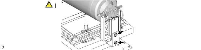
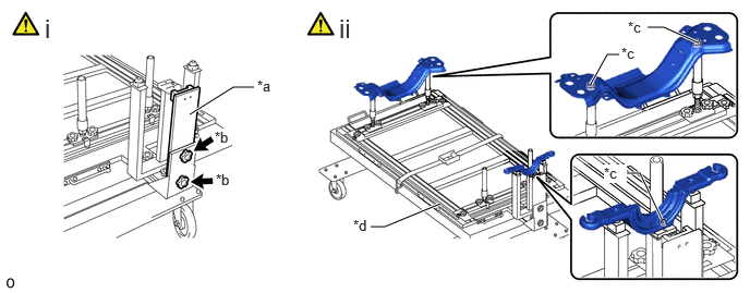
*a SST (Support No. 1) *b SST (Set bolt A)
*c Protrusion *d SST (Hydrogen Tank Stand No. 2)


i.

Install SST (support No. 1) with 2 SST (set bolt A).

SST
09403-62030  (09403-06200, 09403-06210)


ii.

Install the 2 No. 1 hydrogen tank frame sub-assemblies to SST (hydrogen tank stand No. 2)

NOTICE:
·

Align the protrusions of each No. 1 hydrogen tank frame sub-assembly with the holes of SST (support No. 3).

·

Align the protrusion of SST (Support No. 2) with the hole of the lower hydrogen tank bracket.


b.
A477433C02
0.708,1.906 1.063,1.604 1.063,1.604 1.229,1.604 true 4.031,0.813 3.792,0.521 3.792,0.521 3.635,0.521 true 3.927,0.958 3.677,0.958 true 4.198,0.948 4.375,0.948 true 1.26,1.521 1.573,1.677 0.313,0.156 10 true *a 3.469,0.427 3.688,0.573 0.219,0.146 10 true *b 3.5,0.865 3.719,1.01 0.219,0.146 10 true *b 0.385,0.167 0.615,0.417 0.229,0.25 18 false i 2.219,0.156 2.698,0.406 0.479,0.25 18 true ii, iii 4.844,0.167 5.125,0.417 0.281,0.25 18 false iv 4.406,0.854 4.594,1 0.188,0.146 10 true *c
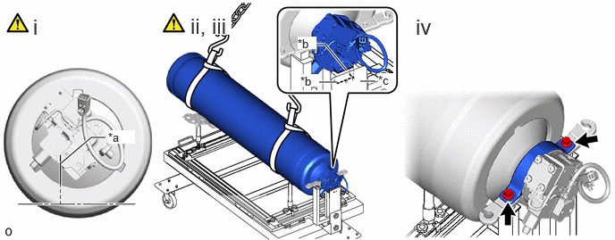
*a Valve Edge *b Make sure there is no gap
*c SST (Support No. 1) - -


i.

Adjust the position of the No. 1 hydrogen tank assembly so that its valve edge is in the vertical direction as shown in the illustration.


ii.

Using the engine sling device and belt, hoist up the No. 1 hydrogen tank assembly.

NOTICE:

Do not allow the No. 1 hydrogen tank assembly to fall.


iii.

Slowly press the valve edge of the No. 1 hydrogen tank assembly against SST (support No. 1), and set the No. 1 hydrogen tank assembly to the No. 1 hydrogen tank frame sub-assembly as shown in the illustration.

NOTICE:
·

To prevent the No. 1 hydrogen tank frame seat from being moved out of position, perform positioning with the No. 1 hydrogen tank assembly lifted up.

·

Make sure that there is no gap between the valve edge of the No. 1 hydrogen tank assembly and SST (support No. 1).


iv.

Install the upper hydrogen tank bracket sub-assembly with the 2 bolts.

Torque:
50 N*m (510 kgf*cm, 37 ft.*lbf)


c.
A477434N02
0.26,0.146 0.49,0.396 0.229,0.25 18 true i 4.563,0.146 4.792,0.396 0.229,0.25 18 true ii

i.

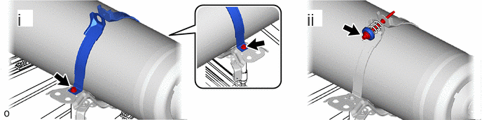
Install the No. 1 hydrogen tank band sub-assembly LH and No. 1 hydrogen tank band sub-assembly RH to the No. 1 hydrogen tank frame sub-assembly with the bolt.

Torque:
50 N*m (510 kgf*cm, 37 ft.*lbf)


ii.

Install the front hydrogen tank spring cup and compression spring with the 2 bolts.

Torque:
50 N*m (510 kgf*cm, 37 ft.*lbf)


d.
A479223N02
1.948,0.042 2.156,0.333 0.208,0.292 18 false i

i.

Remove the 2 SST (set bolt A) and SST (support No. 1).

SST
09403-62030  (09403-06200, 09403-06210)
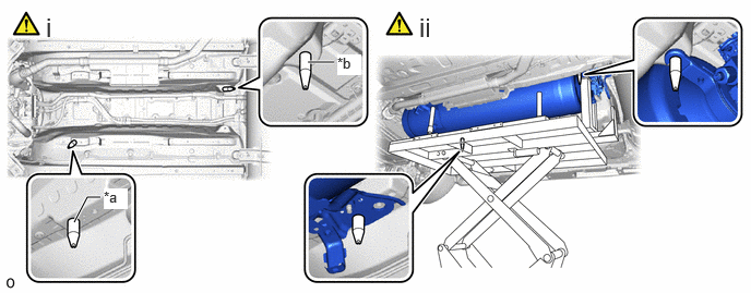


e.
A477435C01
0.708,2.125 0.833,1.885 0.833,1.885 0.958,1.885 true 2.938,0.594 3.188,0.594 true 0.99,1.802 1.219,2 0.229,0.198 10 true *a 3.219,0.521 3.448,0.719 0.229,0.198 10 true *b 0.438,0.115 0.708,0.396 0.271,0.281 18 false i 4,0.115 4.271,0.396 0.271,0.281 18 false ii
*a SST (Guide Pin A) *b SST (Guide Pin B)


i.

Install SST (guide pin A) and SST (guide pin B) as shown in the illustration.

SST
09403-62030  (09403-06270, 09403-06280)


ii.

Operate the engine lifter and slowly install the No. 1 hydrogen tank assembly to the vehicle.


f.
A477436C01
1.969,0.177 2.406,0.438 0.438,0.26 18 true i, iii 2.635,0.177 3.073,0.438 0.438,0.26 18 true i, iii 5.104,2.031 5.542,2.292 0.438,0.26 18 true i, iii 2.552,2.281 2.99,2.542 0.438,0.26 18 true i, iii 1.979,2.26 2.448,2.531 0.469,0.271 18 true ii, iii 5.073,0.365 5.542,0.635 0.469,0.271 18 true ii, iii
V100135

Bolt A
V100136

Bolt B


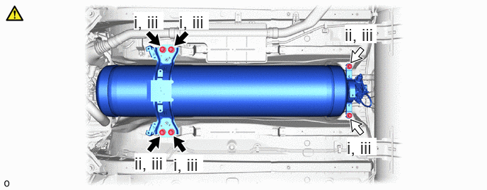
i.

Temporarily install the No. 1 hydrogen tank assembly with the 4 bolts.


ii.

Remove SST (guide pin A) and SST (guide pin B), and install the 2 bolts.

SST
09403-62030  (09403-06270, 09403-06280)


iii.

Tighten the 6 bolts.

Torque:
for bolt A : 73.8 N*m (753 kgf*cm, 54 ft.*lbf)
for bolt B : 83 N*m (846 kgf*cm, 61 ft.*lbf)
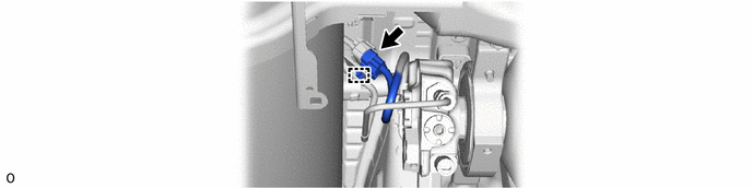


g.
A477404


Hide 77BA5 6.CONNECT NO. 5 HYDROGEN TANK TUBE

Z101186

NOTICE:
·

To protect the seal portions and threaded portions from damage or contamination by foreign matter, remove the protective tape immediately before installation.

·

When reassembling components that have been removed, make sure that there is no foreign matter adhering to the openings.


a.
A479299C03
1.135,0.188 1.323,0.448 0.188,0.26 18 true i 1.125,1.646 1.354,1.885 0.229,0.24 18 true ii 4.563,0.125 5.135,0.406 0.573,0.281 18 true iii, iv 4.427,1.74 4.688,1.906 0.26,0.167 10 false *a
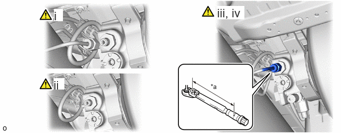
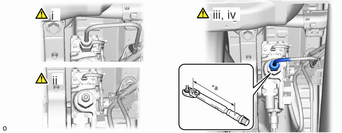
*a Torque Wrench Fulcrum Length - -


i.

To prevent contamination by foreign matter, remove the plastic bags from the openings of the No. 5 hydrogen tank tube immediately before performing the procedure.

NOTICE:

When frost has formed on the hydrogen tank assembly or piping, water droplets may be formed when the frost begins to melt. If water droplets enter the tank or piping, it could result in blockage of the hydrogen piping, so do not allow water droplets to enter the tank or piping.


ii.

To prevent contamination by foreign matter, remove the protective tape from the openings of the No. 1 hydrogen tank assembly immediately before performing the procedure.


iii.

Temporarily install the No. 5 hydrogen tank tube to the No. 1 hydrogen tank assembly with the union nut.


iv.

Using a 19 mm union nut wrench, tighten the union nut while holding a tube part by hand.

Torque:
Specified tightening torque:

25 N*m (255 kgf*cm, 18 ft.*lbf)


HINT:
·

Calculate the torque wrench reading when changing the fulcrum length of the torque wrench.

Click hereGeneral>INTRODUCTION>REPAIR INSTRUCTION>PRECAUTION

·

When using a union nut wrench (fulcrum length of 30 mm (1.18 in.)) + torque wrench (fulcrum length of 180 mm (7.09 in.)): 21.4 N*m (218 kgf*cm, 16 ft.*lbf)


Hide 77BA2 7.CONNECT NO. 2 HYDROGEN TANK TUBE

Z101186

NOTICE:
·

To protect the seal portions and threaded portions from damage or contamination by foreign matter, remove the protective tape immediately before installation.

·

When reassembling components that have been removed, make sure that there is no foreign matter adhering to the openings.


a.
A479300C02
1.073,0.177 1.26,0.438 0.188,0.26 18 true i 1.094,1.542 1.323,1.781 0.229,0.24 18 true ii 4.458,0.156 5.031,0.438 0.573,0.281 18 true iii, iv 4.438,1.76 4.698,1.927 0.26,0.167 10 false *a
*a Torque Wrench Fulcrum Length - -


i.

To prevent contamination by foreign matter, remove the plastic bags from the openings of the No. 2 hydrogen tank tube immediately before performing the procedure.

NOTICE:

When frost has formed on the hydrogen tank assembly or piping, water droplets may be formed when the frost begins to melt. If water droplets enter the tank or piping, it could result in blockage of the hydrogen piping, so do not allow water droplets to enter the tank or piping.


ii.

To prevent contamination by foreign matter, remove the protective tape from the openings of the No. 1 hydrogen tank assembly immediately before performing the procedure.


iii.

Temporarily install the No. 2 hydrogen tank tube to the No. 1 hydrogen tank assembly with the union nut.


iv.

Using a 19 mm union nut wrench, tighten the union nut while holding a tube part by hand.

Torque:
Specified tightening torque:

25 N*m (255 kgf*cm, 18 ft.*lbf)


HINT:
·

Calculate the torque wrench reading when changing the fulcrum length of the torque wrench.

Click hereGeneral>INTRODUCTION>REPAIR INSTRUCTION>PRECAUTION

·

When using a union nut wrench (fulcrum length of 30 mm (1.18 in.)) + torque wrench (fulcrum length of 180 mm (7.09 in.)): 21.4 N*m (218 kgf*cm, 16 ft.*lbf)


Hide 57501C 8.INSTALL FRONT FLOOR BRACE SUB-ASSEMBLY CENTER

Torque:
20 N*m (204 kgf*cm, 15 ft.*lbf)

Hide 9.CONNECT CABLE TO NEGATIVE AUXILIARY BATTERY TERMINAL

Hide 17DB3 11.INSTALL NO. 3 FC EXHAUST PIPE

Hide 12. INITIALIZATION AFTER RECONNECTING BATTERY TERMINAL

Click hereGeneral>SETUP>WHEN DISCONNECTING OR RECONNECTING BATTERY TERMINAL>WORK PROCEDURE

HINT:

When disconnecting and reconnecting the battery, there is an automatic learning function that completes learning when the respective system is used.

Click hereGeneral>SETUP>WHEN DISCONNECTING OR RECONNECTING BATTERY TERMINAL>AUTOMATIC LEARNING CHART


Hide 58398F 14.INSTALL NO. 1 FLOOR UNDER COVER

Hide 57628E 15.INSTALL REAR FLOOR SIDE MEMBER COVER LH

Hide 58401M 16.INSTALL NO. 1 FLOOR BOARD SUB-ASSEMBLY

Z101186

Click here(Click here)

Hide 58402K 17.INSTALL NO. 2 FLOOR BOARD SUB-ASSEMBLY

Z101186

Click here(Click here)

Hide 58403L 18.INSTALL REAR NO. 3 FLOOR BOARD SUB-ASSEMBLY

Hide 58404B 19.INSTALL REAR NO. 4 FLOOR BOARD SUB-ASSEMBLY