FUEL TUBE JOINT(for Inlet Side) INSTALLATION
CAUTION / NOTICE / HINT
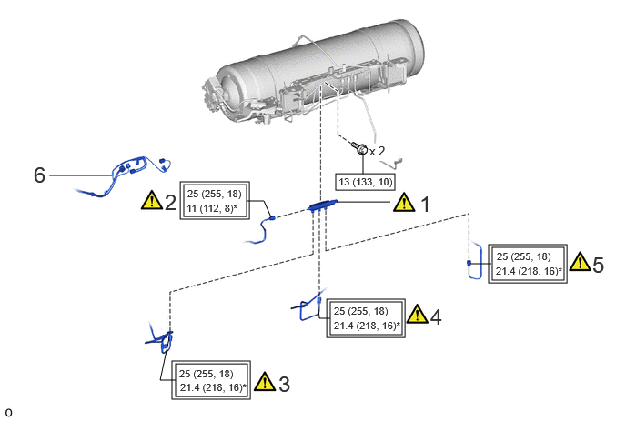
| Procedure | Part Name Code | 
|

|

|
|
|---|---|---|---|---|---|
| 1 | HYDROGEN TANK TUBE JOINT ASSEMBLY | 77BC0 | ( ) |
- | - |
| 2 | NO. 3 HYDROGEN TANK TUBE | 77BA3 | ()
|
- | - |
| 3 | NO. 1 HYDROGEN TANK TUBE | 77BA1 | ()
|
- | - |
| 4 | NO. 4 HYDROGEN TANK TUBE | 77BA4 | ()
|
- | - |
| 5 | NO. 2 HYDROGEN TANK TUBE | 77BA2 | ()
|
- | - |
| 6 | FLOOR WIRE | 82161 | - | - | - |
| *1 | NO. 1 HYDROGEN SUPPLY REGULATOR PLUG | *2 | O-RING |

|
Tightening torque for "Major areas involving basic vehicle performance such as moving/turning/stopping" : N*m (kgf*cm, ft.*lbf) | 
|
N*m (kgf*cm, ft.*lbf): Specified torque |
| * | For use with SST or union nut wrench | - | - |
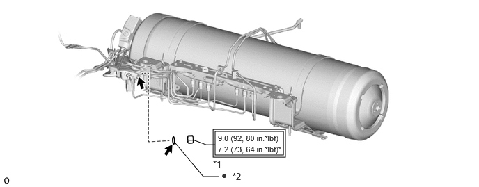
| *1 | NO. 1 HYDROGEN SUPPLY REGULATOR PLUG | *2 | O-RING |
|
|
Tightening torque for "Major areas involving basic vehicle performance such as moving/turning/stopping" : N*m (kgf*cm, ft.*lbf) | * | For use with SST |
| ● | Non-reusable part | 
|
TOYOTA Genuine FC Grease |
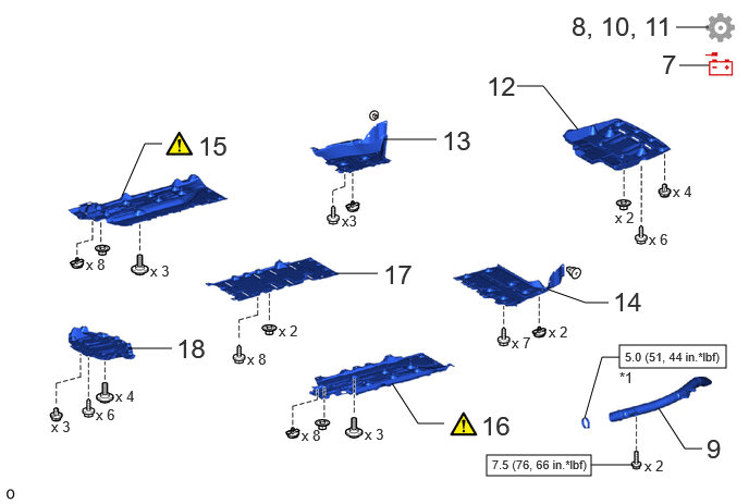
| Procedure | Part Name Code |
|
|
|
|
|---|---|---|---|---|---|
| 7 | CONNECT CABLE TO NEGATIVE AUXILIARY BATTERY TERMINAL | - | - | - | - |
| 8 | FIRST LEAK CHECK | - | - | - | ()
|
| 9 | NO. 3 FC EXHAUST PIPE | 17DB3 | - | - | - |
| 10 | INITIALIZATION AFTER RECONNECTING BATTERY TERMINAL | - | - | - | ()
|
| 11 | SECOND LEAK CHECK | - | - | - | ()
|
| 12 | NO. 1 FLOOR UNDER COVER | 58398F | - | - | - |
| 13 | REAR FLOOR SIDE MEMBER COVER RH | 57627G | - | - | - |
| 14 | REAR FLOOR SIDE MEMBER COVER LH | 57628E | - | - | - |
| 15 | NO. 1 FLOOR BOARD SUB-ASSEMBLY | 58401M | ()
|
- | - |
| 16 | NO. 2 FLOOR BOARD SUB-ASSEMBLY | 58402K | ()
|
- | - |
| 17 | REAR NO. 3 FLOOR BOARD SUB-ASSEMBLY | 58403L | - | - | - |
| 18 | REAR NO. 4 FLOOR BOARD SUB-ASSEMBLY | 58404B | - | - | - |
| *1 | HOSE CLAMP | - | - |
|
|
N*m (kgf*cm, ft.*lbf): Specified torque | - | - |
PROCEDURE

 77BC0
1.INSTALL HYDROGEN TANK TUBE JOINT ASSEMBLY
|
|
|
- Torque:
- 13 N*m (133 kgf*cm, 10 ft.*lbf)
77BA3
2.CONNECT NO. 3 HYDROGEN TANK TUBE
|
|
|
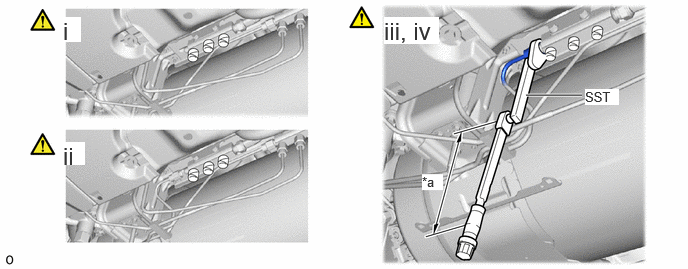
| *a | Torque Wrench Fulcrum Length | - | - |
To prevent contamination by foreign matter, remove the plastic bags from the openings of the No. 3 hydrogen tank tube immediately before performing the procedure.
- NOTICE:
-
When frost has formed on the hydrogen tank assembly or piping, water droplets may be formed when the frost begins to melt. If water droplets enter the tank or piping, it could result in blockage of the hydrogen piping, so do not allow water droplets to enter the tank or piping.
To prevent contamination by foreign matter, remove the protective tape from the openings of the hydrogen tank tube joint assembly immediately before performing the procedure.
Temporarily install the No. 3 hydrogen tank tube to the hydrogen tank tube joint assembly with the union nut.
Using SST and a 19 mm union nut wrench, tighten the union nut while holding a tube part by hand.
- SST
- 09961-01270
- Torque:
- Specified tightening torque:
25 N*m (255 kgf*cm, 18 ft.*lbf)
- HINT:
- ·
Calculate the torque wrench reading when changing the fulcrum length of the torque wrench.
Click hereGeneral>INTRODUCTION>REPAIR INSTRUCTION>PRECAUTION
·When using a union nut wrench (fulcrum length of 30 mm (1.18 in.)) + SST (fulcrum length of 200 mm (7.87 in.)) + torque wrench (fulcrum length of 180 mm (7.09 in.)): 11 N*m (112 kgf*cm, 8 ft.*lbf)
77BA1
3.CONNECT NO. 1 HYDROGEN TANK TUBE
|
|
|
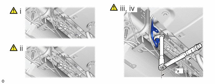
| *a | Torque Wrench Fulcrum Length | - | - |
To prevent contamination by foreign matter, remove the plastic bags from the openings of the No. 1 hydrogen tank tube immediately before performing the procedure.
- NOTICE:
-
When frost has formed on the hydrogen tank assembly or piping, water droplets may be formed when the frost begins to melt. If water droplets enter the tank or piping, it could result in blockage of the hydrogen piping, so do not allow water droplets to enter the tank or piping.
To prevent contamination by foreign matter, remove the protective tape from the openings of the hydrogen tank tube joint assembly immediately before performing the procedure.
Temporarily install the No. 1 hydrogen tank tube to the hydrogen tank tube joint assembly with the union nut.
Using a 19 mm union nut wrench, tighten the union nut while holding a tube part by hand.
- Torque:
- Specified tightening torque:
25 N*m (255 kgf*cm, 18 ft.*lbf)
- HINT:
- ·
Calculate the torque wrench reading when changing the fulcrum length of the torque wrench.
Click hereGeneral>INTRODUCTION>REPAIR INSTRUCTION>PRECAUTION
·When using a union nut wrench (fulcrum length of 30 mm (1.18 in.)) + torque wrench (fulcrum length of 180 mm (7.09 in.)): 21.4 N*m (218 kgf*cm, 16 ft.*lbf)
77BA4
4.CONNECT NO. 4 HYDROGEN TANK TUBE
|
|
|
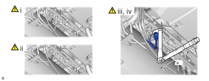
| *a | Torque Wrench Fulcrum Length | - | - |
To prevent contamination by foreign matter, remove the plastic bags from the openings of the No. 4 hydrogen tank tube immediately before performing the procedure.
- NOTICE:
-
When frost has formed on the hydrogen tank assembly or piping, water droplets may be formed when the frost begins to melt. If water droplets enter the tank or piping, it could result in blockage of the hydrogen piping, so do not allow water droplets to enter the tank or piping.
To prevent contamination by foreign matter, remove the protective tape from the openings of the hydrogen tank tube joint assembly immediately before performing the procedure.
Temporarily install the No. 4 hydrogen tank tube to the hydrogen tank tube joint assembly with the union nut.
Using a 19 mm union nut wrench, tighten the union nut while holding a tube part by hand.
- Torque:
- Specified tightening torque:
25 N*m (255 kgf*cm, 18 ft.*lbf)
- HINT:
- ·
Calculate the torque wrench reading when changing the fulcrum length of the torque wrench.
Click hereGeneral>INTRODUCTION>REPAIR INSTRUCTION>PRECAUTION
·When using a union nut wrench (fulcrum length of 30 mm (1.18 in.)) + torque wrench (fulcrum length of 180 mm (7.09 in.)): 21.4 N*m (218 kgf*cm, 16 ft.*lbf)
77BA2
5.CONNECT NO. 2 HYDROGEN TANK TUBE
|
|
|
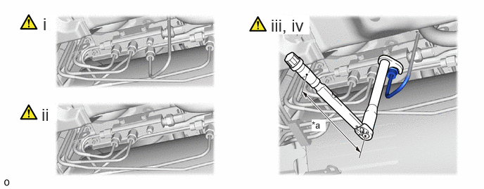
| *a | Torque Wrench Fulcrum Length | - | - |
To prevent contamination by foreign matter, remove the plastic bags from the openings of the No. 2 hydrogen tank tube immediately before performing the procedure.
- NOTICE:
-
When frost has formed on the hydrogen tank assembly or piping, water droplets may be formed when the frost begins to melt. If water droplets enter the tank or piping, it could result in blockage of the hydrogen piping, so do not allow water droplets to enter the tank or piping.
To prevent contamination by foreign matter, remove the protective tape from the openings of the hydrogen tank tube joint assembly immediately before performing the procedure.
Temporarily install the No. 2 hydrogen tank tube to the hydrogen tank tube joint assembly with the union nut.
Using a 19 mm union nut wrench, tighten the union nut while holding a tube part by hand.
- Torque:
- Specified tightening torque:
25 N*m (255 kgf*cm, 18 ft.*lbf)
- HINT:
- ·
Calculate the torque wrench reading when changing the fulcrum length of the torque wrench.
Click hereGeneral>INTRODUCTION>REPAIR INSTRUCTION>PRECAUTION
·When using a union nut wrench (fulcrum length of 30 mm (1.18 in.)) + torque wrench (fulcrum length of 180 mm (7.09 in.)): 21.4 N*m (218 kgf*cm, 16 ft.*lbf)
82161
6.CONNECT FLOOR WIRE
7.CONNECT CABLE TO NEGATIVE AUXILIARY BATTERY TERMINAL
8. FIRST LEAK CHECK
17DB3
9.INSTALL NO. 3 FC EXHAUST PIPE
10. INITIALIZATION AFTER RECONNECTING BATTERY TERMINAL
Click hereGeneral>SETUP>WHEN DISCONNECTING OR RECONNECTING BATTERY TERMINAL>WORK PROCEDURE
- HINT:
-
When disconnecting and reconnecting the battery, there is an automatic learning function that completes learning when the respective system is used.
-
Click hereGeneral>SETUP>WHEN DISCONNECTING OR RECONNECTING BATTERY TERMINAL>AUTOMATIC LEARNING CHART
11. SECOND LEAK CHECK
58398F
12.INSTALL NO. 1 FLOOR UNDER COVER
57627G
13.INSTALL REAR FLOOR SIDE MEMBER COVER RH
57628E
14.INSTALL REAR FLOOR SIDE MEMBER COVER LH
58401M
15.INSTALL NO. 1 FLOOR BOARD SUB-ASSEMBLY
|
|
Click here()
|
58402K
16.INSTALL NO. 2 FLOOR BOARD SUB-ASSEMBLY
|
|
Click here()
|
58403L
17.INSTALL REAR NO. 3 FLOOR BOARD SUB-ASSEMBLY
58404B
18.INSTALL REAR NO. 4 FLOOR BOARD SUB-ASSEMBLY