EXTERIOR PANELS / TRIM FRONT DOOR BELT MOULDING REMOVAL
CAUTION / NOTICE / HINT
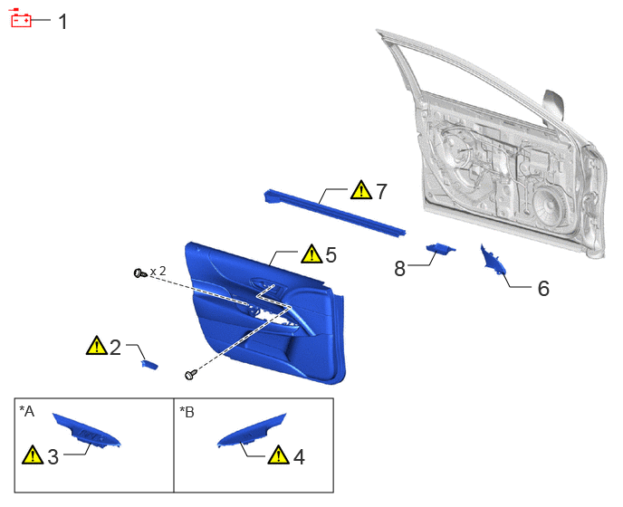
| Procedure | Part Name Code | 
|

|

|
|
|---|---|---|---|---|---|
| 1 | DISCONNECT CABLE FROM NEGATIVE AUXILIARY BATTERY TERMINAL | - | - | - | - |
| 2 | FRONT DOOR INSIDE HANDLE BEZEL PLUG LH | 69284C | ( ) |
- | - |
| 3 | POWER WINDOW REGULATOR MASTER SWITCH ASSEMBLY WITH FRONT DOOR ARMREST BASE PANEL | - | ()
|
- | - |
| 4 | POWER WINDOW REGULATOR SWITCH ASSEMBLY WITH FRONT DOOR ARMREST BASE PANEL | - | ()
|
- | - |
| 5 | FRONT DOOR TRIM BOARD SUB-ASSEMBLY LH | 67602 | ()
|
- | - |
| 6 | FRONT DOOR LOWER FRAME BRACKET GARNISH LH | 67492A | - | - | - |
| 7 | FRONT DOOR INNER GLASS WEATHERSTRIP LH | 68172A | ()
|
- | - |
| 8 | FRONT DOOR FRONT BELT SEAL LH | 68193C | - | - | - |
| *A | for Driver Side | *B | for Front Passenger Side |
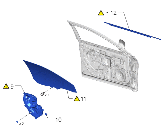
| Procedure | Part Name Code |
|
|
|
|
|---|---|---|---|---|---|
| 9 | FRONT DOOR SERVICE HOLE COVER LH | 67832 | ()
|
- | - |
| 10 | HOLE PLUG | - | - | - | - |
| 11 | FRONT DOOR GLASS SUB-ASSEMBLY LH | 68102 | ()
|
- | - |
| 12 | FRONT DOOR BELT MOULDING ASSEMBLY LH | 75720 | ()
|
- | - |
| ● | Non-reusable part | - | - |
CAUTION / NOTICE / HINT
The necessary procedures (adjustment, calibration, initialization or registration) that must be performed after parts are removed, installed or replaced during the front door belt moulding assembly removal/installation are shown below.
| Replaced Part or Performed Procedures | Necessary Procedures | Effect/Inoperative Function when Necessary Procedures are not Performed | Link |
|---|---|---|---|
| Disconnect cable from negative (-) auxiliary battery terminal | Memorize steering angle neutral point | Parking assist monitor system | ()
|
| Panoramic view monitor system | ()
|
||
·
Front door glass (RH, LH) or front door glass run (RH, LH) ·
Because of assembly adjustment, etc., causing sliding change, improper reversal has occurred |
Power window system initialization | ·
Auto up and down function ·
Jam protection function ·
Catch protection function ·
Remote control function ·
Key-linked function ·
Wireless transmitter-linked function ·
Key-off operation function ·
Window open warning function |
()
|
- HINT:
- ·
When the cable is disconnected/reconnected to the auxiliary battery terminal, systems temporarily stop operating. However, each system has a function that completes learning the first time the system is used.
-Learning completes when vehicle is driven
Effect/Inoperative Function When Necessary Procedures are not Performed Necessary Procedures Link Lane tracing assist system Drive the vehicle straight ahead at 35 km/h (22 mph) or more for 5 seconds or more. ( )
Pre-collision system Adaptive high beam system
-Learning completes when vehicle is operated normally
Effect/Inoperative Function When Necessary Procedures are not Performed Necessary Procedures Link Air conditioning system After the ignition switch is turned to ON, the servo motor and expansion valve standard position is recognized. -
·Use the same procedure for the RH and LH sides.
·The procedure described below is for the LH side.
PROCEDURE

 1.DISCONNECT CABLE FROM NEGATIVE AUXILIARY BATTERY TERMINAL
69284C
2.REMOVE FRONT DOOR INSIDE HANDLE BEZEL PLUG LH
|
|
Click here()
|
3.REMOVE POWER WINDOW REGULATOR MASTER SWITCH ASSEMBLY WITH FRONT DOOR ARMREST BASE PANEL (for Driver Side)
|
|
Click here()
|
4.REMOVE POWER WINDOW REGULATOR SWITCH ASSEMBLY WITH FRONT DOOR ARMREST BASE PANEL (for Front Passenger Side)
|
|
Click here()
|
67602
5.REMOVE FRONT DOOR TRIM BOARD SUB-ASSEMBLY LH
|
|
Click here()
|
67492A
6.REMOVE FRONT DOOR LOWER FRAME BRACKET GARNISH LH
68172A
7.REMOVE FRONT DOOR INNER GLASS WEATHERSTRIP LH
|
|
Click here()
|
68193C
8.REMOVE FRONT DOOR FRONT BELT SEAL LH
67832
9.REMOVE FRONT DOOR SERVICE HOLE COVER LH
|
|
Click here()
|
10.REMOVE HOLE PLUG
68102
11.REMOVE FRONT DOOR GLASS SUB-ASSEMBLY LH
|
|
Click here()
|
75720
12.REMOVE FRONT DOOR BELT MOULDING ASSEMBLY LH
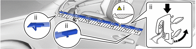

|
Remove in this Direction | 
|
Push in this Direction |
Put protective tape around the front door belt moulding assembly LH.
Detach the claw and remove the front door belt moulding assembly LH as shown in the illustration.