FC CONTROL FC CONTROL SYSTEM P1DB511 Medium-Range Hydrogen Pressure Sensor Circuit Short to Ground P1DB515 Medium-Range Hydrogen Pressure Sensor Circuit Short to Battery or Open
DESCRIPTION
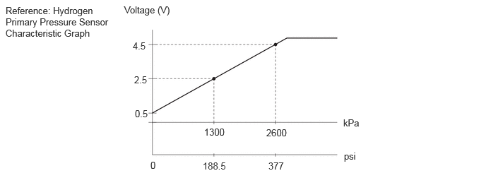
The hydrogen primary pressure sensor is provided on the hydrogen supply primary pipe sub-assembly, and it detects and converts hydrogen pressure in the hydrogen supply system (medium-range pressure area) into voltage values.
The FC control ECU checks for leaks in the hydrogen supply system (medium-range pressure area) when the FC system is activated, and monitors pressure in the hydrogen supply system (medium-range pressure area) as well as checks the tank internal pressure (whether the tank has run out of hydrogen) while the FC system is in operation, through use of hydrogen primary pressure sensor values.
| DTC No. | Detection Item | DTC Detection Condition | Trouble Area | Warning Indicate | DTC Output from | Priority |
|---|---|---|---|---|---|---|
| P1DB511 | Medium-Range Hydrogen Pressure Sensor Circuit Short to Ground | If the +B voltage is not low when the ignition switch is ON, the output voltage of the hydrogen primary pressure sensor circuit remains at less than 0.10 V for more than 3 seconds.
(1 trip detection logic) |
·
Hydrogen primary pressure sensor ·
FC control ECU ·
Wire harness or connector |
Master Warning: Comes on | FC | A |
| P1DB515 | Medium-Range Hydrogen Pressure Sensor Circuit Short to Battery or Open | If the +B voltage is not low when the ignition switch is ON, the output voltage of the hydrogen primary pressure sensor circuit remains at more than 4.85V for more than 3 seconds.
(1 trip detection logic) |
·
Hydrogen primary pressure sensor ·
FC control ECU ·
Wire harness or connector |
Master Warning: Comes on | FC | A |
| Vehicle Condition | FC shutdown
(ignition switch ON) |
FC startup process | FC intermittent operation | FC is generating power
(vehicle is in stationary) |
FC is generating power
(vehicle is traveling) |
FC shutdown process |
|---|---|---|---|---|---|---|
| Data List (EV)
"FC Work Mode" |
Stop | Startup | Working | Finishing | ||
| Data List (EV)
"FC Intermittent Operation" |
OFF | ON | OFF | OFF | ||
| DTC Detection | ○ | ○ | ○ | ○ | ○ | - |
| DTC No. | Data List |
|---|---|
| P1DB511 | Medium-Range Hydrogen Pressure Sensor Voltage |
| P1DB515 |
- HINT:
-
If DTCs are found, read the "Medium-Range Hydrogen Pressure Sensor Voltage" in the Data List on a GTS.
| Medium-Range Hydrogen Pressure Sensor Voltage | Malfunction |
|---|---|
| Less than 0.10 V | ·
Open in VHPM (5 V power supply) circuit ·
Short in HPM circuit to ground ·
Short in HPM circuit to GHPM (GND) circuit |
| Higher than 4.85 V | ·
Short in VHPM circuit to HPM circuit ·
Open in HPM circuit ·
Open in GHPM (GND) circuit ·
Short in VHPM circuit to ground |
- HINT:
-
It is suspected that malfunctions, or open/short circuits have occurred in the hydrogen primary pressure sensor.
WIRING DIAGRAM
CAUTION / NOTICE / HINT
- NOTICE:
- ·
This vehicle performs FC system shutdown process after turning the ignition switch off from ON (READY). Therefore, after the ignition switch is turned off from ON (READY), do not perform any work on the electrical system for at least 10 minutes including removing connectors or disconnecting the negative (-) auxiliary battery terminal.
·When the EV control ECU determines that the temperature of FC system components is below 0°C (32°F) when the vehicle is parked with the ignition switch off, it operates the FC air compressor, hydrogen pump and FC cooling water pump for a maximum of 180 seconds to drain the FC stack assembly. When performing inspection or repairs with the ignition switch off (not ON or ON (READY)), disconnect the cable from the negative (-) auxiliary battery terminal before performing work. (If the auxiliary battery voltage is needed to conduct inspection, perform the inspection in an environment with an ambient temperature of 10°C (50°F) or higher.)
- HINT:
-
After the repair, clear the DTCs and perform the following procedure to check that DTCs are not output.
- 1.
Turn the ignition switch to ON and wait for 3 seconds or more.
PROCEDURE
Pre-procedure1
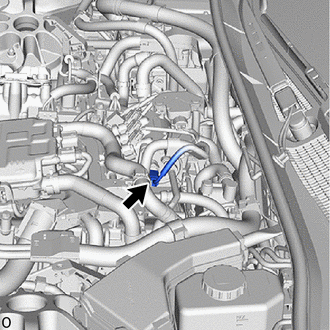
Disconnect the hydrogen primary pressure sensor connector.
Turn the ignition switch to ON.
Procedure1
Measure the voltage according to the value(s) in the table below.
- Standard Voltage:
Tester Connection Condition Specified Condition Click Location & Routing(B10)Location & Routingewd_type=routing;type=c;code=B10
Click Connector(B10)Engine Compartment>No. 2 Stack Wire>Hydrogen Primary Pressure Sensorewd_type=component;type=c;code=B10;pinno=3,1
B10-3 (VHPM) - B10-1 (GHPM) Ignition switch ON 4.75 to 5.25 V B10-3 (HPM) - B10-1 3(GHPM) Ignition switch ON 4.75 to 5.25 V
- Result:
Proceed to OK NG
Post-procedure1
Turn the ignition switch off.
Reconnect the hydrogen primary pressure sensor connector.
OK
NG
Pre-procedure1
Disconnect the FC control ECU connector.
Disconnect the hydrogen primary pressure sensor connector.
Procedure1
Measure the resistance according to the value(s) in the table below.
- Standard Resistance:
Tester Connection Condition Specified Condition Click Location & Routing(B1,B10)Location & Routingewd_type=routing;type=c,c;code=B1,B10
Click Connector(B1)Engine Compartment>No. 2 Stack Wire>FC Control ECUewd_type=component;type=c;code=B1;pinno=112,113,114
Click Connector(B10)Engine Compartment>No. 2 Stack Wire>Hydrogen Primary Pressure Sensorewd_type=component;type=c;code=B10;pinno=2,1,3
B1-112 (HPM) - B10-2 (HPM) Always Below 1 Ω B1-113 (GHPM) - B10-1 (GHPM) Always Below 1 Ω B1-114 (VHPM) - B10-3 (VHPM) Always Below 1 Ω B1-112 (HPM) or B10-2 (HPM) - Body ground and other terminals Always 10 kΩ or higher B1-114 (VHPM) or B10-3 (VHPM) - Body ground and other terminals Always 10 kΩ or higher
- Result:
Proceed to OK NG
Post-procedure1
Reconnect the hydrogen primary pressure sensor connector.
Reconnect the FC control ECU connector.
OK
NG
- Result:
Proceed to NEXT
NEXT
Pre-procedure1
None
Procedure1
Clear the DTCs.
- Powertrain > FC > Clear DTCs
- 50002 490
- Result:
Proceed to NEXT
Post-procedure1
Turn the ignition switch off and wait for 10 minutes or more.
NEXT
Pre-procedure1
None
Procedure1
Check for DTCs.
- Powertrain > FC > Trouble Codes
- 50001 490
- Result:
Result Proceed to P1DB511 or P1DB515 is output A DTCs are not output B
Post-procedure1
Turn the ignition switch off.
A
B
Pre-procedure1
Disconnect the hydrogen primary pressure sensor connector.
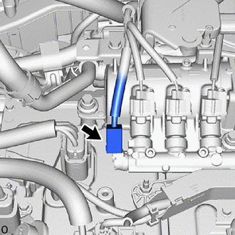
Disconnect the hydrogen secondary pressure sensor connector.
Turn the ignition switch to ON.
Procedure1
Measure the voltage according to the value(s) in the table below.
- Standard Voltage:
Tester Connection Condition Specified Condition Click Location & Routing(B10)Location & Routingewd_type=routing;type=c;code=B10
Click Connector(B10)Engine Compartment>No. 2 Stack Wire>Hydrogen Primary Pressure Sensorewd_type=component;type=c;code=B10;pinno=3,1
B10-3 (VHPM) - B10-1 (GHPM) Ignition switch ON 4.75 to 5.25 V B10-3 (HPM) - B10-1 3(GHPM) Ignition switch ON 4.75 to 5.25 V
- Result:
Proceed to OK NG
Post-procedure1
Turn the ignition switch off.
Reconnect the hydrogen secondary pressure sensor connector.
Reconnect the hydrogen primary pressure sensor connector.
OK
NG
Pre-procedure1
Disconnect the hydrogen primary pressure sensor connector.
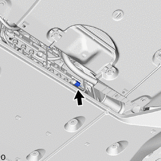
Disconnect the hydrogen tank pressure sensor (for outlet side) connector.
Turn the ignition switch to ON.
Procedure1
Measure the voltage according to the value(s) in the table below.
- Standard Voltage:
Tester Connection Condition Specified Condition Click Location & Routing(B10)Location & Routingewd_type=routing;type=c;code=B10
Click Connector(B10)Engine Compartment>No. 2 Stack Wire>Hydrogen Primary Pressure Sensorewd_type=component;type=c;code=B10;pinno=3,1
B10-3 (VHPM) - B10-1 (GHPM) Ignition switch ON 4.75 to 5.25 V B10-3 (HPM) - B10-1 3(GHPM) Ignition switch ON 4.75 to 5.25 V
- Result:
Proceed to OK NG
Post-procedure1
Turn the ignition switch off.
Reconnect the hydrogen tank pressure sensor (for outlet side) connector.
Reconnect the hydrogen primary pressure sensor connector.
OK
NG
Pre-procedure1
Disconnect the FC control ECU connector.
Disconnect the hydrogen primary pressure sensor connector.
Procedure1
Measure the resistance according to the value(s) in the table below.
- Standard Resistance:
Tester Connection Condition Specified Condition Click Location & Routing(B1,B10)Location & Routingewd_type=routing;type=c,c;code=B1,B10
Click Connector(B1)Engine Compartment>No. 2 Stack Wire>FC Control ECUewd_type=component;type=c;code=B1;pinno=112,113,114
Click Connector(B10)Engine Compartment>No. 2 Stack Wire>Hydrogen Primary Pressure Sensorewd_type=component;type=c;code=B10;pinno=2,1,3
B1-112 (HPM) - B10-2 (HPM) Always Below 1 Ω B1-113 (GHPM) - B10-1 (GHPM) Always Below 1 Ω B1-114 (VHPM) - B10-3 (VHPM) Always Below 1 Ω B1-112 (HPM) or B10-2 (HPM) - Body ground and other terminals Always 10 kΩ or higher B1-114 (VHPM) or B10-3 (VHPM) - Body ground and other terminals Always 10 kΩ or higher
- Result:
Proceed to OK NG
Post-procedure1
Reconnect the hydrogen primary pressure sensor connector.
Reconnect the FC control ECU connector.
OK
NG
Pre-procedure1
Disconnect the FC control ECU connector.
Disconnect the hydrogen secondary pressure sensor connector.
Procedure1
Measure the resistance according to the value(s) in the table below.
- Standard Resistance:
Tester Connection Condition Specified Condition Click Location & Routing(B1,B11)Location & Routingewd_type=routing;type=c,c;code=B1,B11
Click Connector(B1)Engine Compartment>No. 2 Stack Wire>FC Control ECUewd_type=component;type=c;code=B1;pinno=68
Click Connector(B11)Engine Compartment>No. 2 Stack Wire>Hydrogen Secondary Pressure Sensorewd_type=component;type=c;code=B11;pinno=3
B1-68 (VHPL) - B11-3 (VHPL) Always Below 1 Ω B1-68 (VHPL) or B11-3 (VHPL) - Body ground and other terminals Always 10 kΩ or higher
- Result:
Proceed to OK NG
Post-procedure1
Reconnect the hydrogen secondary pressure sensor connector.
Reconnect the FC control ECU connector.
OK
NG
Pre-procedure1
Disconnect the FC control ECU connector.
Disconnect the hydrogen tank pressure sensor (for outlet side) connector.
Procedure1
Measure the resistance according to the value(s) in the table below.
- Standard Resistance:
Tester Connection Condition Specified Condition Click Location & Routing(B1,G7)Location & Routingewd_type=routing;type=c,c;code=B1,G7
Click Connector(B1)Engine Compartment>No. 2 Stack Wire>FC Control ECUewd_type=component;type=c;code=B1;pinno=115
Click Connector(G7)Body>Floor Wire / No. 3 Floor Wire>Hydrogen Tank Pressure Sensorewd_type=component;type=c;code=G7;pinno=3
B1-115 (VHPT) - G7-3 (VHPT) Always Below 1 Ω B1-115 (VHPT) or G7-3 (VHPT) - Body ground and other terminals Always 10 kΩ or higher
- Result:
Proceed to OK NG
Post-procedure1
Reconnect the hydrogen tank pressure sensor (for outlet side) connector.
Reconnect the FC control ECU connector.
OK
NG