FC CONTROL FC CONTROL SYSTEM P1DC300 Medium-Range Hydrogen Pressure Too High
DESCRIPTION
The hydrogen system of the FC system feeds the FC stack with hydrogen, so that the FC stack can generate power. In the hydrogen system, from the hydrogen supply regulator assembly (high-pressure regulator) to the hydrogen injectors are a group of components in the medium-range hydrogen pressure circuit.
The hydrogen supply regulator assembly mechanically depressurizes the tank original pressure that varies according to consumption, in order to regulate it to a specified medium-range pressure. If the medium-range hydrogen pressure has exceeded a threshold, the EV control ECU interprets that there is something wrong with the medium-range pressure components, and stores this DTC.
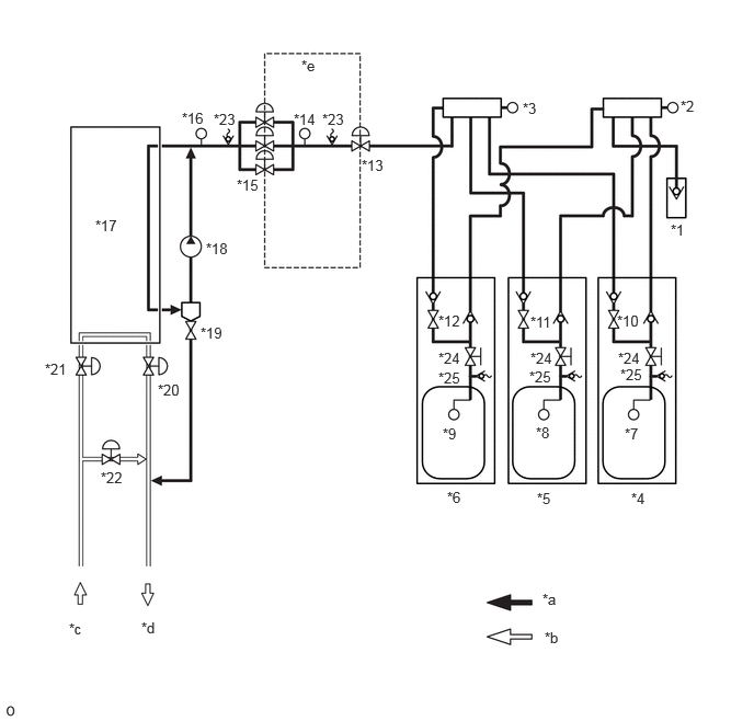
| *1 | Hydrogen Inlet Receptacle Assembly | *2 | Hydrogen Tank Pressure Sensor (for Inlet Side) |
| *3 | Hydrogen Tank Pressure Sensor (for Outlet Side) | *4 | No. 1 Hydrogen Tank Assembly |
| *5 | No. 2 Hydrogen Tank Assembly | *6 | No. 3 Hydrogen Tank Assembly |
| *7 | Hydrogen Tank Temperature Sensor 1 | *8 | Hydrogen Tank Temperature Sensor 2 |
| *9 | Hydrogen Tank Temperature Sensor 3 | *10 | Tank Shut Valve 1 |
| *11 | Tank Shut Valve 2 | *12 | Tank Shut Valve 3 |
| *13 | Hydrogen Supply Regulator Assembly | *14 | Hydrogen Primary Pressure Sensor |
| *15 | Fuel Injector Assembly | *16 | Hydrogen Secondary Pressure Sensor |
| *17 | FC Stack | *18 | Hydrogen Recirculation Pump Assembly |
| *19 | Exhaust Drainage Valve (Hydrogen Recirculation Separator Assembly) | *20 | FC Air Pressure Regulator Assembly (Air Pressure Regulating Valve) |
| *21 | FC Air Pressure Regulator Assembly (Air Sealing Valve) | *22 | FC Air By-pass Valve Assembly (Air Shunt Valve) |
| *23 | Pressure Relief Valve | *24 | Manual Valve |
| *25 | Pressure Relief Device | - | - |
| *a | Hydrogen System | *b | Air System |
| *c | From the FC Air Compressor with Motor Assembly | *d | To the Exhaust Drainage Pipe |
| *e | Medium-range Hydrogen Pressure Circuit | - | - |
| DTC No. | Detection Item | DTC Detection Condition | Trouble Area | Warning Indicate | DTC Output from | Priority |
|---|---|---|---|---|---|---|
| P1DC300 | Medium-Range Hydrogen Pressure Too High | Medium-range hydrogen pressure has exceeded a threshold. This malfunction detection is active while the ignition switch is ON (READY)(modes other than FC shutdown).
(1 trip detection logic) |
·
Hydrogen supply regulator assembly ·
Hydrogen primary pressure sensor ·
Medium-range hydrogen pressure pipe |
Master Warning: Comes on | EV | B |
| Vehicle Condition | FC shutdown
(ignition switch ON) |
FC startup process | FC intermittent operation | FC is generating power
(vehicle is in stationary) |
FC is generating power
(vehicle is traveling) |
FC shutdown process |
|---|---|---|---|---|---|---|
| Data List
"FC Work Mode" |
Stop | Startup | Working | Finishing | ||
| Data List
"FC Intermittent Operation" |
OFF | ON | OFF | OFF | ||
| DTC Detection | - | ○ | ○ | ○ | ○ | ○ |
- HINT:
-
By accessing the "FC Work Mode" and "FC Intermittent Operation" in the freeze frame data, the FC system condition at the time the malfunction occurred can be checked.
| DTC No. | Data List |
|---|---|
| P1DC300 | ·
Medium-Range Hydrogen Pressure (Filtered Value) ·
Motor Room Hydrogen Density ·
Tank Area 1 Hydrogen Density ·
Tank Area 2 Hydrogen Density ·
High-Range Hydrogen Pressure (Filtered Value) ·
Low-Range Hydrogen Pressure (Filtered Value) |
CAUTION / NOTICE / HINT
- CAUTION:
-
- ·
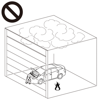
Work procedures must be performed in an area with good ventilation (airflow) where hydrogen gas will not accumulate, and flames or other things that could act as ignition sources must not be present.
·Accumulated hydrogen gas could ignite, resulting in a serious accident.
Click hereEngine / Hybrid System>FUEL>FUEL SYSTEM>PRECAUTION
- NOTICE:
- ·
This vehicle performs FC system shutdown process after turning the ignition switch off from ON (READY). Therefore, after the ignition switch is turned off from ON (READY), do not perform any work on the electrical system for at least 10 minutes including removing connectors or disconnecting the negative (-) auxiliary battery terminal.
·When the EV control ECU determines that the temperature of FC system components is below 0°C (32°F) when the vehicle is parked with the ignition switch off, it operates the FC air compressor, hydrogen pump and FC cooling water pump for a maximum of 180 seconds to drain the FC stack assembly. When performing inspection or repairs with the ignition switch off (not ON or ON (READY)), disconnect the cable from the negative (-) auxiliary battery terminal before performing work. (If the auxiliary battery voltage is needed to conduct inspection, perform the inspection in an environment with an ambient temperature of 10°C (50°F) or higher.)
- HINT:
-
After the repair, clear the DTCs and perform the following procedure to check that DTCs are not output.
- 1.
Put the state in park (P) and turn the ignition switch to ON (READY), and then wait for at least 2 minutes with the FC Work Mode of the Data List in modes other than "FC Shutdown".
2.Check that no hydrogen leaks from the hydrogen system components with a hydrogen gas detector.
PROCEDURE
- NOTICE:
-
The freeze frame data is cleared when DTCs are cleared. Be sure to make a note of necessary data in advance.
Pre-procedure1
None
Procedure1
According to the display on the GTS, check for DTCs in the Health Check.
- Result:
Result Proceed to Only P1DC300 is output A P1DC300 is output and DTCs other than the DTCs in the table below are output B P1DC300 is output and any DTCs in the table below are output C
Malfunction Content Relevant DTC Sensor and actuator circuit malfunction P1DB511 (FC) Medium-Range Hydrogen Pressure Sensor Circuit Short to Ground P1DB515 (FC) Medium-Range Hydrogen Pressure Sensor Circuit Short to Battery or Open
- HINT:
-
DTC P1DC300 may be store due to problems that cause the DTCs shown above to be output. If such happens, troubleshoot the suspected area(s) corresponding to the output DTC(s) in order starting with the listed DTCs shown in the table above.
Post-procedure1
Turn the ignition switch off.
A
B
C
Pre-procedure1
None
Procedure1
Clear the DTCs.
- Powertrain > EV > Clear DTCs
- 50002 397
- Result:
Proceed to NEXT
Post-procedure1
Turn the ignition switch off and wait for 10 minutes or more.
NEXT
Pre-procedure1
None
Procedure1
Using the GTS snapshot, record the values of the Data List items listed below.
- Powertrain > EV > Data List
-
Tester Display Medium-Range Hydrogen Pressure (Filtered Value) Low-Range Hydrogen Pressure (Filtered Value) - 50003 397 1031,1032
Turn the ignition switch to ON (READY).
Check the recorded snapshot data.
- Result:
Result Proceed to "Medium-Range Hydrogen Pressure (Filtered Value)" is 1600 kPa (abs) or higher and "Low-Range Hydrogen Pressure (Filtered Value)" increases even once. A "Medium-Range Hydrogen Pressure (Filtered Value)" is 1600 kPa (abs) or higher and "Low-Range Hydrogen Pressure (Filtered Value)" does not change. B Other than above. C
- HINT:
-
If "Low-Range Hydrogen Pressure (Filtered Value)" does not change, the hydrogen injector is not operating.
Post-procedure1
Turn the ignition switch off.
A
B
C
Click hereGeneral>INTRODUCTION>HOW TO TROUBLESHOOT ECU CONTROLLED SYSTEMS>HOW TO PROCEED WITH TROUBLESHOOTING
Pre-procedure1
Remove the hydrogen primary pressure sensor (medium-range hydrogen pressure sensor).
Reconnect the hydrogen primary pressure sensor (medium-range hydrogen pressure sensor) connector.
Procedure1
Read the value displayed on the GTS.
- Powertrain > EV > Data List
-
Tester Display Medium-Range Hydrogen Pressure (Filtered Value) - 50003 397 1031
Using the table, read the normal atmospheric pressure value for the applicable altitude.
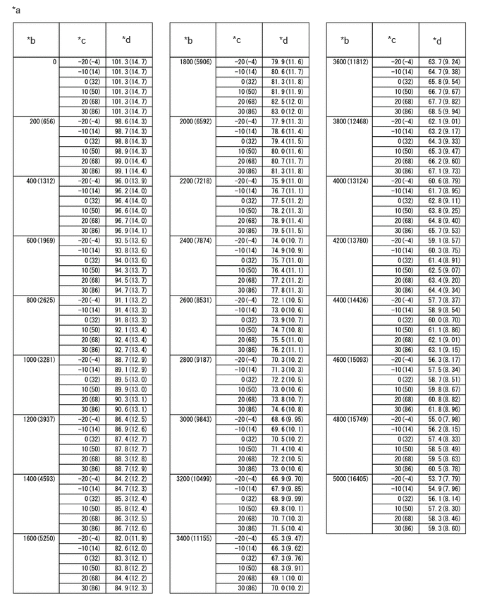
| *a | Altitude, Temperature and Atmospheric Pressure Correlation Table | *b | Altitude (m (ft.)) |
| *c | Temperature (°C (°F)) | *d | Atmospheric Pressure (kPa (psi)) |
- HINT:
- ·
Standard atmospheric pressure is approximately 101 kPa (15 psi).
·For every 100 m (328 ft.) increase in altitude, atmospheric pressure drops by approximately 1 kPa (0.1 psi). This varies by weather.
Compare the "Medium-Range Hydrogen Pressure (Filtered Value)" values in the Data List with the normal atmospheric value from the table.
- Result:
Result Proceed to Difference between "Medium-Range Hydrogen Pressure (Filtered Value)" in Data List and normal atmospheric pressure value is 100 kPa or more. A Other than above. B
Post-procedure1
Turn the ignition switch off.
A
B