FC CONTROL FC CONTROL SYSTEM Fuel Lid Interlock Circuit
DESCRIPTION
The EV control ECU monitors the fuel lid condition (open/close) by means of the interlock switch that is built into the fuel lid with motor lock assembly. If the interlock switch signal indicates that the fuel lid is open, the EV control ECU prohibits the ignition switch from being turned to ON (READY) during hydrogen filling.
If it is found that the fuel lid is open with the ignition switch off, the EV control ECU prohibits the ignition switch from being turned to ON (READY) and also the shift state from being changed from P to other positions.
If the vehicle is in the READY ON mode, even when the open fuel lid is detected, the EV control ECU allows the vehicle to remain in the READY ON mode. However, if the hydrogen tank internal pressure increases due to hydrogen filling when the vehicle is in the READY ON mode, the EV control ECU forcibly stops the FC system.
Despite the fact that the fuel lid is actually closed, if the multi-information display shows "Open Filler Door Detected Close Hydrogen Filler Door Restart Vehicle" or "Open Filler Door Detected Stop in a Safe Place Close Hydrogen Filler Door", perform this diagnostic troubleshooting procedure.
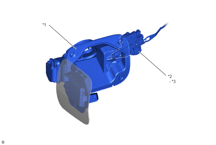
| *1 | Fuel Filler Opening Lid Sub-assembly | *2 | Fuel Lid with Motor Lock Assembly |
| *3 | Interlock Switch | - | - |
WIRING DIAGRAM
Refer to DTC P1E6B73.
Click hereEngine / Hybrid System>FC CONTROL>FC CONTROL SYSTEM>P1E6B73
CAUTION / NOTICE / HINT
- NOTICE:
- ·
This vehicle performs FC system shutdown process after turning the ignition switch off from ON (READY). Therefore, after the ignition switch is turned off from ON (READY), do not perform any work on the electrical system for at least 10 minutes including removing connectors or disconnecting the negative (-) auxiliary battery terminal.
·When the EV control ECU determines that the temperature of FC system components is below 0°C (32°F) when the vehicle is parked with the ignition switch off, it operates the FC air compressor, hydrogen pump and FC cooling water pump for a maximum of 180 seconds to drain the FC stack assembly. When performing inspection or repairs with the ignition switch off (not ON or ON (READY)), disconnect the cable from the negative (-) auxiliary battery terminal before performing work. (If the auxiliary battery voltage is needed to conduct inspection, perform the inspection in an environment with an ambient temperature of 10°C (50°F) or higher.)
- HINT:
-
Related Data List
Fuel Lid Interlock Switch
Tester Display Fuel lid fully closed Fuel lid fully open Fuel Lid Interlock Switch OFF ON
- Suspected malfunctions·
Fuel lid with motor lock assembly is stuck closed or open.
·Fuel lid with motor lock assembly circuit has an open, or is shorted to the GND circuit.
PROCEDURE
Click hereVehicle Exterior>DOOR / HATCH>FUEL LID OPENER MOTOR ASSEMBLY>INSPECTION
- Result:
Proceed to OK NG
OK
NG
Disconnect the EV control ECU connector.
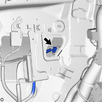
Disconnect the fuel lid with motor lock assembly (interlock switch) connector.
Measure the resistance according to the value(s) in the table below.
- Standard Resistance (for LHD):
Tester Connection Condition Specified Condition Click Location & Routing(G70,G14)Location & Routingewd_type=routing;type=c,c;code=G70,G14
Click Connector(G70)Body>Floor Wire / No. 3 Floor Wire>Fuel Lid Lock with Motor Assemblyewd_type=component;type=c;code=G70;pinno=3
Click Connector(G14)Instrument Panel>Floor Wire>EV Control ECUewd_type=component;type=c;code=G14;pinno=5
G70-3 (B) - G14-5 (FILK) Always Below 1 Ω G70-3 (B) or G14-5 (FILK) - Body ground and other terminals Always 10 kΩ or higher
- Standard Resistance (for RHD):
Tester Connection Condition Specified Condition Click Location & Routing(G70,A14)Location & Routingewd_type=routing;type=c,c;code=G70,A14
Click Connector(G70)Body>Floor Wire / No. 3 Floor Wire>Fuel Lid Lock with Motor Assemblyewd_type=component;type=c;code=G70;pinno=3
Click Connector(A14)Instrument Panel>Front Compartment Main Wire>EV Control ECUewd_type=component;type=c;code=A14;pinno=5
G70-3 (B) - A14-5 (FILK) Always Below 1 Ω G70-3 (B) or A14-5 (FILK) - Body ground and other terminals Always 10 kΩ or higher
Reconnect the fuel lid with motor lock assembly (interlock switch) connector.
Reconnect the EV control ECU connector.
- Result:
Proceed to OK NG
OK
NG
Disconnect the fuel lid with motor lock assembly (interlock switch) connector.
Measure the resistance according to the value(s) in the table below.
- Standard Resistance:
Tester Connection Condition Specified Condition Click Location & Routing(G70)Location & Routingewd_type=routing;type=c;code=G70
Click Connector(G70)Body>Floor Wire / No. 3 Floor Wire>Fuel Lid Lock with Motor Assemblyewd_type=component;type=c;code=G70;pinno=2
G70-2 (E) - Body ground Always Below 1 Ω
Reconnect the fuel lid with motor lock assembly (interlock switch) connector.
- Result:
Proceed to OK NG
OK
NG