STEERING COLUMN HEATED STEERING WHEEL SYSTEM B14B7 Lost Communication with Steering Heater ECU
DESCRIPTION
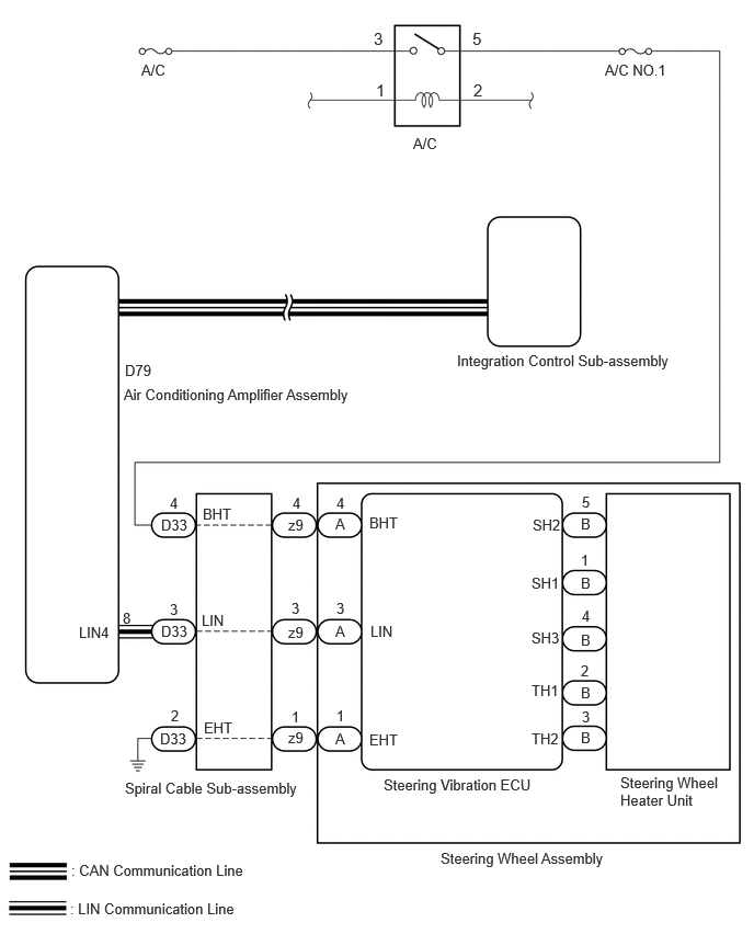
The steering vibration ECU communicates with the air conditioning amplifier assembly via LIN communication.
B14B7 is output when a communication malfunction is detected with the air conditioner amplifier assembly and steering vibration ECU.
| DTC No. | Detection Item | DTC Detection Condition | Trouble Area | DTC Output from | Priority |
|---|---|---|---|---|---|
| B14B7 | Lost Communication with Steering Heater ECU | ·
Diagnosis condition: Ignition switch ON ·
Malfunction status: Lost communication with air conditioning amplifier assembly and steering vibration ECU ·
Detection time: Continuously for 10 seconds or more |
·
Steering vibration ECU ·
Air conditioning amplifier assembly ·
Spiral cable sub-assembly ·
Harness or connector |
Air Conditioner | A |
WIRING DIAGRAM
CAUTION / NOTICE / HINT
- NOTICE:
- ·
Inspect the fuses for circuits related to this system before performing the following procedure.
·The vehicle is equipped with a Supplemental Restraint System (SRS) which includes components such as airbags. Before servicing (including removal or installation of parts), be sure to read the precaution for Supplemental Restraint System.
Click hereVehicle Interior>SUPPLEMENTAL RESTRAINT SYSTEMS>AIRBAG SYSTEM>PRECAUTION
PROCEDURE
Pre-procedure1
Disconnect the D33 spiral cable sub-assembly connector.
Procedure1
Measure the voltage according to the value(s) in the table below.
- Standard Voltage:
Tester Connection Condition Specified Condition Click Location & Routing(D33)Location & Routingewd_type=routing;type=c;code=D33
Click Connector(D33)Instrument Panel>Instrument Panel Wire>Spiral Cable Sub-Assemblyewd_type=component;type=c;code=D33;pinno=4
D33-4 (BHT) - Body ground Ignition switch ON 11 to 14 V D33-4 (BHT) - Body ground Ignition switch off Below 1 V
- Result:
Proceed to OK NG
Post-procedure1
None
OK
NG
Pre-procedure1
Disconnect the D33 spiral cable sub-assembly connector.
Procedure1
Measure the resistance according to the value(s) in the table below.
- Standard Resistance:
Tester Connection Condition Specified Condition Click Location & Routing(D33)Location & Routingewd_type=routing;type=c;code=D33
Click Connector(D33)Instrument Panel>Instrument Panel Wire>Spiral Cable Sub-Assemblyewd_type=component;type=c;code=D33;pinno=2
D33-2 (EHT) - Body ground Always Below 1 Ω
- Result:
Proceed to OK NG
Post-procedure1
None
OK
NG
Click hereVehicle Interior>SUPPLEMENTAL RESTRAINT SYSTEMS>SPIRAL CABLE>INSPECTION
- Result:
Proceed to OK NG
OK
NG
Pre-procedure1
Disconnect the D33 spiral cable sub-assembly connector.
Disconnect the D79 air conditioning amplifier assembly connector.
Procedure1
Measure the resistance according to the value(s) in the table below.
- Standard Resistance:
Tester Connection Condition Specified Condition Click Location & Routing(D33,D79)Location & Routingewd_type=routing;type=c,c;code=D33,D79
Click Connector(D33)Instrument Panel>Instrument Panel Wire>Spiral Cable Sub-Assemblyewd_type=component;type=c;code=D33;pinno=3
Click Connector(D79)Instrument Panel>Instrument Panel Wire>Air Conditioning Amplifier Assemblyewd_type=component;type=c;code=D79;pinno=8
D33-3 (LIN) - D79-8 (LIN4) Always Below 1 Ω D33-3 (LIN) or D79-8 (LIN4) - Other terminals and body ground Always 10 kΩ or higher
- Result:
Proceed to OK NG
Post-procedure1
None
OK
NG
Pre-procedure1
Disconnect the D33 spiral cable sub-assembly connector.
Procedure1
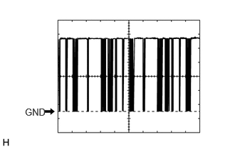
Using an oscilloscope, check the waveform.
| Tester Connection | Tool Setting | Switch Condition |
|---|---|---|
|
Click Location & Routing(D33)Location & Routingewd_type=routing;type=c;code=D33 Click Connector(D33)Instrument Panel>Instrument Panel Wire>Spiral Cable Sub-Assemblyewd_type=component;type=c;code=D33;pinno=3 |
||
| D33-3 (LIN) - Body ground | 2 V/DIV., 20 ms/DIV. | Ignition switch ON |
- OK:
The waveform displays properly.
- NOTICE:
-
Oscilloscope waveform samples are provided here for informational purposes. Noise and fluttering waveforms have been omitted.
- Result:
Proceed to OK NG
Post-procedure1
None
OK
NG