SUPPLEMENTAL RESTRAINT SYSTEMS SPIRAL CABLE REMOVAL
CAUTION / NOTICE / HINT
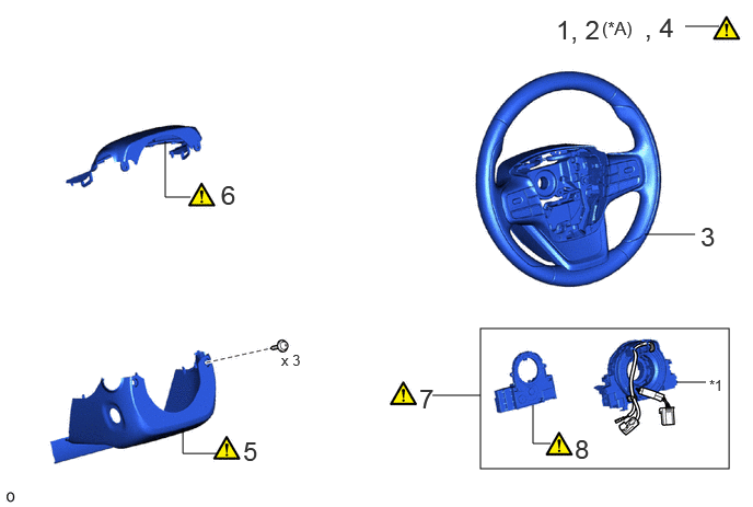
| Procedure | Part Name Code | 
|

|

|
|
|---|---|---|---|---|---|
| 1 | PRECAUTION | - | ( ) |
- | - |
| 2 | CUSTOMIZE POWER TILT AND POWER TELESCOPIC STEERING COLUMN SYSTEM | - | ()
|
- | - |
| 3 | STEERING WHEEL ASSEMBLY | 45100 | - | - | - |
| 4 | INSPECT SPIRAL CABLE WITH SENSOR SUB-ASSEMBLY | - | ()
|
- | - |
| 5 | LOWER STEERING COLUMN COVER | 45287 | ()
|
- | - |
| 6 | UPPER STEERING COLUMN COVER | 45286B | ()
|
- | - |
| 7 | SPIRAL CABLE WITH SENSOR SUB-ASSEMBLY | - | ()
|
- | - |
| 8 | STEERING SENSOR | - | ()
|
- | - |
| *A | for Power Tilt and Power Telescopic Steering Column | - | - |
| *1 | SPIRAL CABLE SUB-ASSEMBLY | - | - |
CAUTION / NOTICE / HINT
The necessary procedures (adjustment, calibration, initialization or registration) that must be performed after parts are removed and installed, or replaced during the spiral cable with sensor sub-assembly removal/installation are shown below.
| Replaced Part or Performed Procedure | Necessary Procedure | Effect/Inoperative Function when Necessary Procedure not Performed | Link |
|---|---|---|---|
| Disconnect cable from negative auxiliary battery terminal | Memorize steering angle neutral point | Parking Assist Monitor System | ()
|
| Panoramic View Monitor System | ()
|
||
| Steering sensor (Including removal and installation) | Steering angle neutral point | Parking assist monitor system | ()
|
| Panoramic view monitor system | ()
|
- HINT:
-
When the cable is disconnected/reconnected to the auxiliary battery terminal, systems temporarily stop operating. However, each system has a function that completes learning the first time the system is used.
- ·
Learning completes when vehicle is driven
Effect/Inoperative Function When Necessary Procedures are not Performed Necessary Procedures Link Lane tracing assist system Drive the vehicle straight ahead at 35 km/h (22 mph) or more for 5 seconds or more. ( )
Pre-collision system Adaptive high beam system
·Learning completes when vehicle is operated normally
Effect/Inoperative Function When Necessary Procedures are not Performed Necessary Procedures Link Air conditioning system After the ignition switch is turned to ON, the servo motor and expansion valve standard position is recognized. -
·Use the same procedure for RHD and LHD vehicles.
·The procedure listed below is for LHD vehicles.
PROCEDURE

 1. PRECAUTION
|
|
|
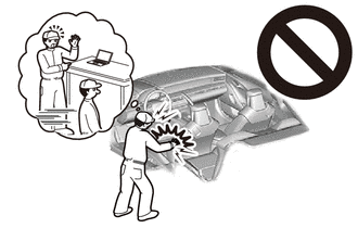
2. CUSTOMIZE POWER TILT AND POWER TELESCOPIC STEERING COLUMN SYSTEM (for Power Tilt and Power Telescopic Steering Column)
|
|
|
Perform the customization settings.
Click hereSteering>STEERING COLUMN>POWER TILT AND POWER TELESCOPIC STEERING COLUMN SYSTEM>CUSTOMIZE PARAMETERS
Move the steering wheel to its lowest and rearmost position.
45100
3.REMOVE STEERING WHEEL ASSEMBLY
4.INSPECT SPIRAL CABLE WITH SENSOR SUB-ASSEMBLY
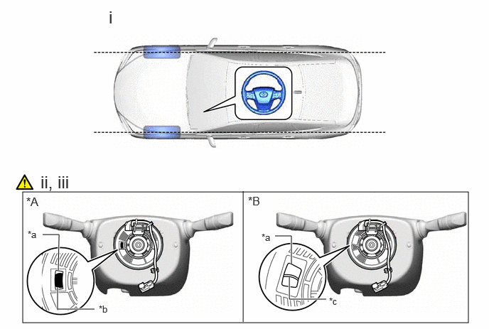
| *A | Colored Roller (Visible Type) | *B | Flat Cable (Visible Type) |
| *a | Check Window | *b | Colored Roller |
| *c | Top of Flat Cable U-turn | - | - |
Check that the front wheels are facing straight ahead.
Check that the spiral cable with sensor sub-assembly is center position.
- OK:
The connector is at the top.
The colored roller or the top of the flat cable U-turn can be checked from the check window.
If the result is not as specified, it is possible that the spiral cable sub-assembly is broken. Replace the spiral cable sub-assembly with a new one.
45287
5.REMOVE LOWER STEERING COLUMN COVER
|
|
Click here()
|
45286B
6.REMOVE UPPER STEERING COLUMN COVER
|
|
Click here()
|
7.REMOVE SPIRAL CABLE WITH SENSOR SUB-ASSEMBLY
|
|
|
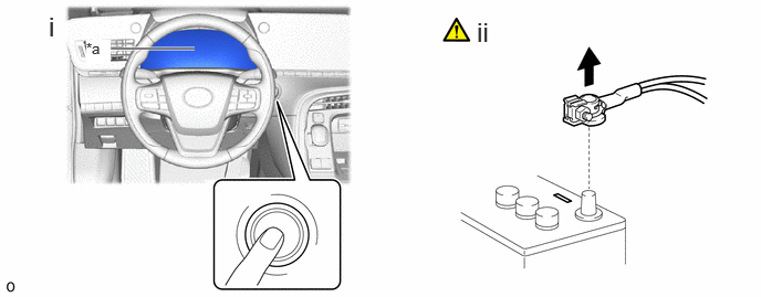
| *a | Turns off | - | - |
Check that the ignition switch is off.
Check that the cable is disconnected from the negative (-) auxiliary battery terminal.
- CAUTION:
- ·
Wait at least 60 seconds after disconnecting the cable from the negative (-) auxiliary battery terminal to disable the SRS system.
·If the airbag deploys for any reason, it may cause a serious accident.
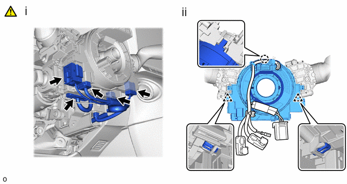
Disconnect the 5 connectors.
- HINT:
-
Refer to How to Connect or Disconnect Airbag Connector: Click hereVehicle Interior>SUPPLEMENTAL RESTRAINT SYSTEMS>AIRBAG SYSTEM>HOW TO CONNECT OR DISCONNECT AIRBAG CONNECTOR
Detach the claw and clip and remove the spiral cable with sensor sub-assembly.
8.REMOVE STEERING SENSOR
|
|
|
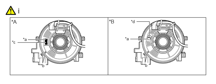
| *A | Colored Roller (Visible Type) | *B | Flat Cable (Visible Type) |
| *a | Check Window | *b | Matchmark |
| *c | Colored Roller | *d | Top of Flat Cable U-turn |
Check that the spiral cable with sensor sub-assembly is centered.
- HINT:
-
If the spiral cable with sensor sub-assembly is not centered, center it.
-
Click hereVehicle Interior>SUPPLEMENTAL RESTRAINT SYSTEMS>SPIRAL CABLE>INSTALLATION
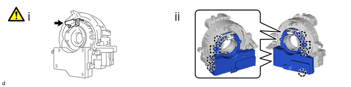
Install the lock pin to the steering sensor.
- NOTICE:
- ·
Use the lock pin provided with a new spiral cable.
·Do not remove the lock pin before the spiral cable is installed to the steering sensor.
Detach the claw and guide to remove the steering sensor from the spiral cable sub-assembly.