FC CONTROL FCDC CONVERTER CONTROL ECU BOARD REMOVAL
CAUTION / NOTICE / HINT
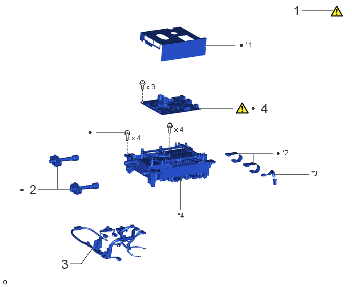
| Procedure | Part Name Code | 
|

|

|
|
|---|---|---|---|---|---|
| 1 | PRE-CHECK | - | ( ) |
- | - |
| 2 | FC CONVERTER COOLING PIPE | G9A43 | - | - | - |
| 3 | NO. 1 FC CONVERTER WIRE | G9A1C | - | - | - |
| 4 | FCDC CONVERTER CONTROL ECU BOARD SUB-ASSEMBLY | F160A | ()
|
- | - |
| *1 | FC CONVERTER SHEET | *2 | ECU WIRE SUB-ASSEMBLY |
| *3 | NO. 3 FC CONVERTER WIRE | *4 | FC CONVERTER POWER MODULE TRANSISTOR (IPM) |
| ● | Non-reusable part | - | - |
PROCEDURE

 1. PRE-CHECK
- CAUTION:
-
- ·
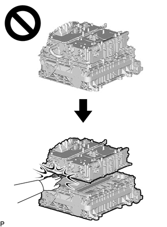
Since high voltage accumulates within the FC stack assembly with FC converter, never perform the work of disassembling the FC converter assembly itself or internal parts without first performing electrical charge discharge (forced electrical charge discharge or electrical charge self-discharge), because the high voltage circuit could cause electric shock.
·Never perform work with the FC converter assembly installed in the vehicle.
·Never perform work if the FC converter assembly is not standing alone.
- HINT:
-
Check "Pre-work" prior to working in order to perform work safely.
Pre-work
Electrical charge discharge (forced electrical charge discharge or electrical charge self-discharge) must have been performed.
Click hereEngine / Hybrid System>FC CONTROL>FC STACK>REMOVAL
The FC stack assembly with FC converter with front frame assembly must have been removed from the vehicle.
Click hereEngine / Hybrid System>FC CONTROL>FC STACK>REMOVAL
The FC converter assembly must be standing alone.
Click hereEngine / Hybrid System>FC CONTROL>CONVERTER ASSEMBLY>REMOVAL
G9A43
2.REMOVE FC CONVERTER COOLING PIPE
G9A1C
3.DISCONNECT NO. 1 FC CONVERTER WIRE

F160A
4.REMOVE FCDC CONVERTER CONTROL ECU BOARD SUB-ASSEMBLY
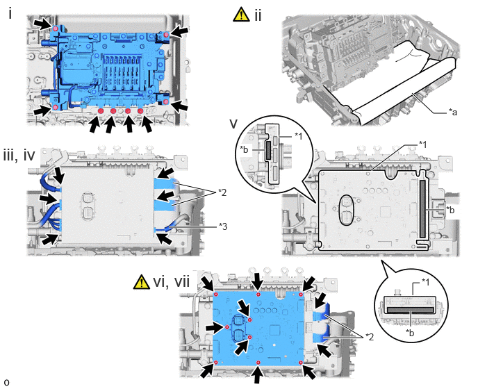
| *1 | FC Converter Sheet | *2 | ECU Wire Sub-assembly |
| *3 | NO. 3 FC Converter Wire | - | - |
| *a | Cloth, etc. | *b | Double-side Tape |
Remove the 8 bolts.
Set a cloth, etc. inside the FC converter assembly as shown in the illustration.
- HINT:
-
When placing the FC converter power module transistor (IPM) against the FC converter case sub-assembly, place a cloth, etc. so that the FC converter power module transistor (IPM) and case are not damaged.
Disconnect the 5 connecters.
- NOTICE:
-
Do not apply excessive force to the FCDC converter control ECU board sub-assembly connector.
Disconnect the connector and remove the No. 3 FC converter wire.
- NOTICE:
-
Do not apply excessive force to the FCDC converter control ECU board sub-assembly connector.
Double-sided tape is applied at the area shown in the illustration. Remove the tape and FC converter sheet.
Disconnect the 2 connectors and remove the 2 ECU wire sub-assemblies.
- NOTICE:
-
Do not apply excessive force to the FCDC converter control ECU board sub-assembly connector.
Using the magnetic screwdriver of the FC converter power module transistor kit, remove the 9 screws and FCDC converter control ECU board sub-assembly.