INTERIOR PANELS / TRIM FRONT CONSOLE BOX REMOVAL
CAUTION / NOTICE / HINT
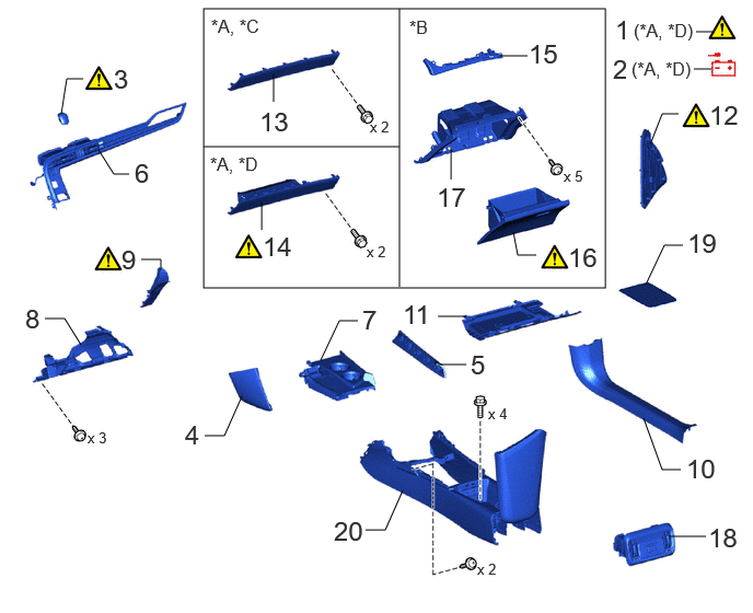
| Procedure | Part Name Code | 
|

|

|
|
|---|---|---|---|---|---|
| 1 | PRECAUTION | - | ( ) |
- | - |
| 2 | DISCONNECT CABLE FROM NEGATIVE AUXILIARY BATTERY TERMINAL | - | ()
|
- | - |
| 3 | SHIFT LEVER KNOB SUB-ASSEMBLY | 33504F | ()
|
- | - |
| 4 | UPPER NO. 1 CONSOLE PANEL GARNISH | 58833B | - | - | - |
| 5 | UPPER NO. 2 CONSOLE PANEL GARNISH | 58834B | - | - | - |
| 6 | INSTRUMENT CLUSTER FINISH PANEL GARNISH ASSEMBLY | 55470 | - | - | - |
| 7 | REAR UPPER CONSOLE PANEL SUB-ASSEMBLY | - | - | - | - |
| 8 | NO. 1 INSTRUMENT PANEL UNDER COVER SUB-ASSEMBLY | 55606 | - | - | - |
| 9 | LOWER INSTRUMENT PANEL FINISH PANEL SUB-ASSEMBLY LH | 55046A | ()
|
- | - |
| 10 | FRONT DOOR SCUFF PLATE RH | 67913 | - | - | - |
| 11 | NO. 2 INSTRUMENT PANEL UNDER COVER SUB-ASSEMBLY | 55607 | - | - | - |
| 12 | NO. 2 INSTRUMENT SIDE PANEL | 55318F | ()
|
- | - |
| 13 | INSTRUMENT PANEL FINISH PANEL END RH | 55435A | - | - | - |
| 14 | LOWER NO. 2 INSTRUMENT PANEL AIRBAG ASSEMBLY | 73990 | ()
|
||
| 15 | LOWER INSTRUMENT CLUSTER FINISH PANEL GARNISH | 55479D | - | - | - |
| 16 | GLOVE COMPARTMENT DOOR SUB-ASSEMBLY | 55501A | ()
|
- | - |
| 17 | LOWER NO. 2 INSTRUMENT PANEL FINISH PANEL | 55433B | - | - | - |
| 18 | CONSOLE REAR END PANEL SUB-ASSEMBLY | 58903A | - | - | - |
| 19 | CONSOLE BOX CARPET | 58815C | - | - | - |
| 20 | CONSOLE BOX ASSEMBLY | 58810J | - | - | - |
| *A | for LHD | *B | for RHD |
| *C | w/o Passenger Side Knee Airbag | *D | w/ Passenger Side Knee Airbag |
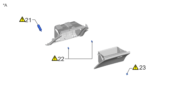
| Procedure | Part Name Code |
|
|
|
|
|---|---|---|---|---|---|
| 21 | GLOVE COMPARTMENT DOOR STOPPER SUB-ASSEMBLY | 55054 | ()
|
- | - |
| 22 | GLOVE COMPARTMENT DOOR CHECK CUSHION | 55557A | ()
|
- | - |
| 23 | GLOVE COMPARTMENT DOOR LOCK CYLINDER ASSEMBLY | 69550A | ()
|
- | - |
| *A | for RHD | - | - |
CAUTION / NOTICE / HINT
The necessary procedures (adjustment, calibration, initialization or registration) that must be performed after parts are removed and installed, or replaced during console box assembly removal/installation are shown below.
| Replaced Parts or Performed Procedures | Necessary Procedures | Effect/Inoperative Function When Necessary Procedure are not Performed | Link |
|---|---|---|---|
| Disconnect cable from negative auxiliary battery terminal | Memorize steering angle neutral point | Parking Assist Monitor System | ()
|
| Panoramic View Monitor System | ()
|
- HINT:
- ·
When the cable is disconnected/reconnected to the auxiliary battery terminal, systems temporarily stop operating. However, each system has a function that completes learning the first time the system is used.
-Learning completes when vehicle is driven
Effect/Inoperative Function When Necessary Procedures are not Performed Necessary Procedures Link Lane tracing assist system Drive the vehicle straight ahead at 35 km/h (22 mph) or more for 5 second or more. ( )
Pre-collision system Adaptive high beam system
-Learning completes when vehicle is operated normally
Effect/Inoperative Function When Necessary Procedures are not Performed Necessary Procedures Link Air conditioning system After the ignition switch is turned to ON, the servo motor and expansion valve standard position is recognized. -
·Use the same procedure for RHD and LHD vehicles.
·The procedure listed below is for LHD vehicles.
PROCEDURE

 1. PRECAUTION (for LHD, w/ Passenger Side Knee Airbag)
|
|
|
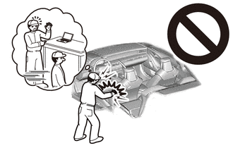
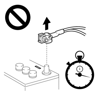
2.DISCONNECT CABLE FROM NEGATIVE AUXILIARY BATTERY TERMINAL (for LHD, w/ Passenger Side Knee Airbag)
|
|
|
33504F
3.REMOVE SHIFT LEVER KNOB SUB-ASSEMBLY
|
|
Click here()
|
58833B
4.REMOVE UPPER NO. 1 CONSOLE PANEL GARNISH
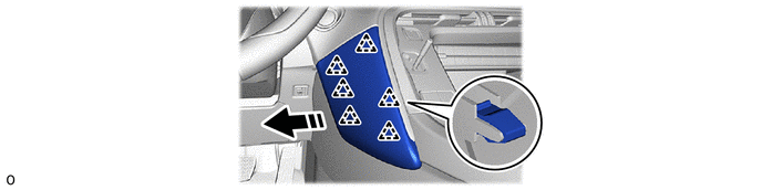

|
Remove in this Direction | - | - |
58834B
5.REMOVE UPPER NO. 2 CONSOLE PANEL GARNISH
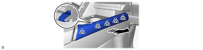
|
|
Remove in this Direction | - | - |
55470
6.REMOVE INSTRUMENT CLUSTER FINISH PANEL GARNISH ASSEMBLY
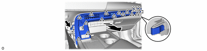
|
|
Remove in this Direction | - | - |
7.REMOVE REAR UPPER CONSOLE PANEL SUB-ASSEMBLY
- HINT:
-
The illustrations are representative examples, and details may differ.
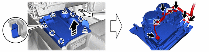
|
|
Remove in this Direction (1) | 
|
Remove in this Direction (2) |
55606
8.REMOVE NO. 1 INSTRUMENT PANEL UNDER COVER SUB-ASSEMBLY
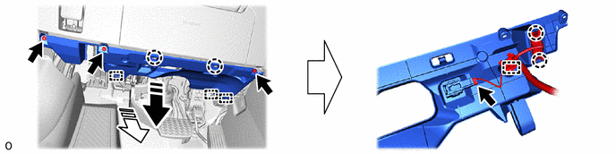
|
|
Remove in this Direction (1) |
|
Remove in this Direction (2) |
55046A
9.REMOVE LOWER INSTRUMENT PANEL FINISH PANEL SUB-ASSEMBLY LH
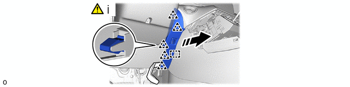
|
|
Remove in this Direction | - | - |
Using moulding remover A, detach the clip as shown in the illustration and remove the lower instrument panel finish panel sub-assembly LH.
67913
10.REMOVE FRONT DOOR SCUFF PLATE RH
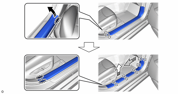

|
Place Hand Here |
|
Remove in this Direction (1) |
|
|
Remove in this Direction (2) | 
|
Remove in this Direction (3) |
55607
11.REMOVE NO. 2 INSTRUMENT PANEL UNDER COVER SUB-ASSEMBLY
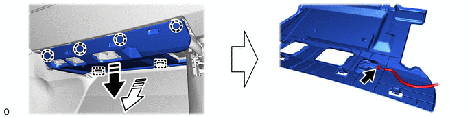
|
|
Remove in this Direction (1) |
|
Remove in this Direction (2) |
55318F
12.REMOVE NO. 2 INSTRUMENT SIDE PANEL
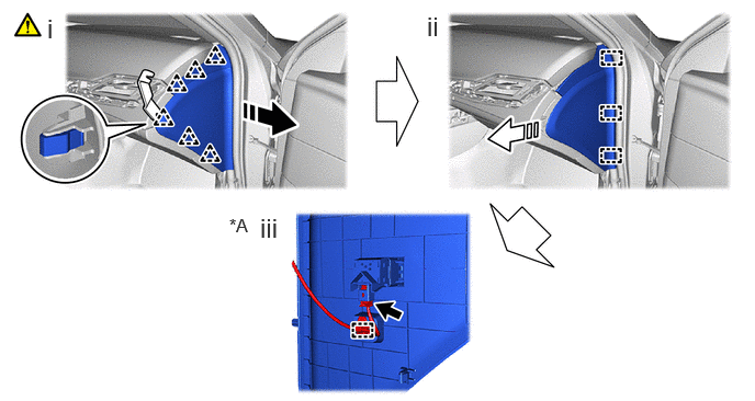
| *A | w/ Airbag Cut Off Switch | - | - |
|
|
Remove in this Direction (1) |
|
Remove in this Direction (2) |
Using moulding remover B, detach the clip in the removal direction (1) as shown in the illustration.
Detach the guide in the removal direction (2) as shown in the illustration and remove the No. 2 instrument side panel.
w/ Airbag Cut Off Switch:
1. Detach the clamp and disconnect the connector.
55435A
13.REMOVE INSTRUMENT PANEL FINISH PANEL END RH (for LHD, w/o Passenger Side Knee Airbag)
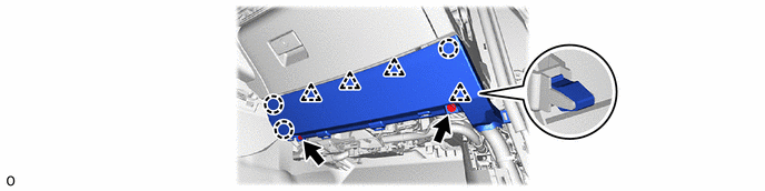
73990
14.REMOVE LOWER NO. 2 INSTRUMENT PANEL AIRBAG ASSEMBLY (for LHD, w/ Passenger Side Knee Airbag)
|
|
Click here()
|
55479D
15.REMOVE LOWER INSTRUMENT CLUSTER FINISH PANEL GARNISH (for RHD)
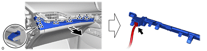
|
|
Remove in this Direction | - | - |
55501A
16.REMOVE GLOVE COMPARTMENT DOOR SUB-ASSEMBLY (for RHD)
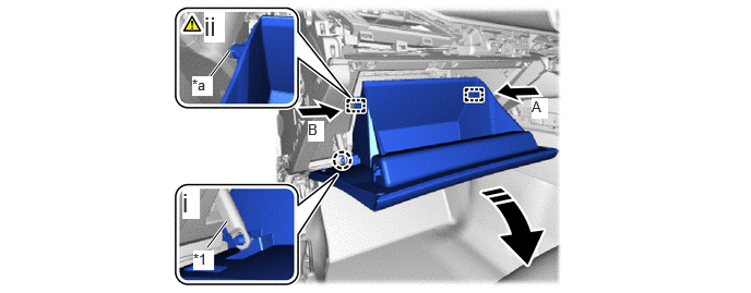
| *1 | Glove Compartment Door Stopper Sub-assembly | - | - |
| *a | Stopper | - | - |
|
|
Remove in this Direction | - | - |
Detach the claw and disconnect the glove compartment door stopper sub-assembly.
Slightly bend the stoppers (A) and (B) in the directions indicated by the arrows in the illustration and open the glove compartment door assembly until the stoppers are released.
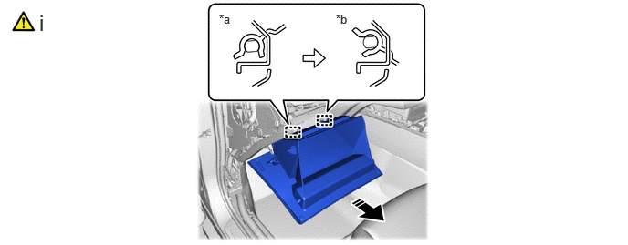
| *a | Closed Position | *b | Horizontal Position |
|
|
Remove in this Direction | - | - |
Pull the glove compartment door assembly horizontally in the direction indicated by the arrow to detach the hinges and remove it.
- NOTICE:
-
Pulling the glove compartment door assembly upward to remove it causes the hinges to deform. Be sure to pull out the glove compartment door assembly horizontally.
55433B
17.REMOVE LOWER NO. 2 INSTRUMENT PANEL FINISH PANEL (for RHD)
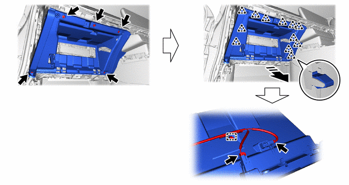
|
|
Remove in this Direction | - | - |
58903A
18.REMOVE CONSOLE REAR END PANEL SUB-ASSEMBLY
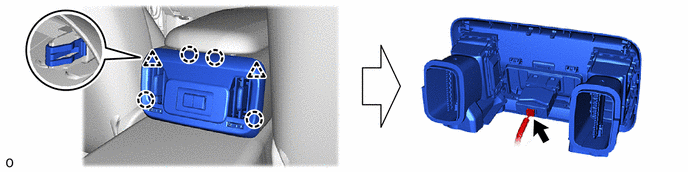
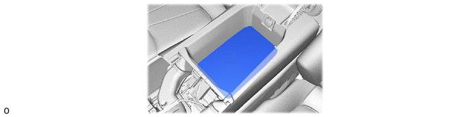
58815C
19.REMOVE CONSOLE BOX CARPET
58810J
20.REMOVE CONSOLE BOX ASSEMBLY
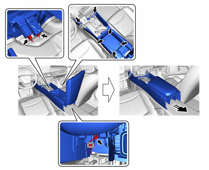
|
|
Remove in this Direction | - | - |
55054
21.REMOVE GLOVE COMPARTMENT DOOR STOPPER SUB-ASSEMBLY (for RHD)
|
|
|

55557A
22.REMOVE GLOVE COMPARTMENT DOOR CHECK CUSHION (for RHD)
|
|
|
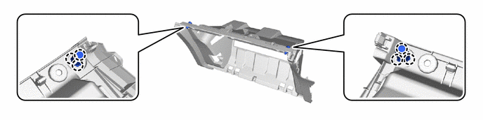
69550A
23.REMOVE GLOVE COMPARTMENT DOOR LOCK CYLINDER ASSEMBLY (for RHD)
|
|
|
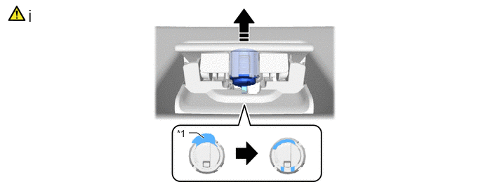
| *1 | Cylinder Lock | - | - |
|
|
Remove in this Direction | - | - |
Press the cylinder lock to release it and pull out the glove compartment door lock cylinder assembly from the glove compartment door assembly to remove it as shown in the illustration.