HYBRID / BATTERY CONTROL HYBRID BATTERY SYSTEM P056014 System Voltage (BATT) Circuit Short to Ground or Open
DESCRIPTION
Auxiliary battery power is supplied to the AM terminal of the battery ECU assembly in order to store DTCs and freeze frame data. Even if the ignition switch is turned off, back-up power is supplied.
| DTC No. | Detection Item | DTC Detection Condition | Trouble Area | Warning Indicate | DTC Output from | Priority |
|---|---|---|---|---|---|---|
| P056014 | System Voltage (BATT) Circuit Short to Ground or Open | Malfunction in the battery ECU assembly back-up power source circuit
(1 trip detection logic) |
·
Wire harness or connector ·
Battery ECU assembly ·
Fuse |
Master Warning:
Comes on |
EV Battery | A |
CONFIRMATION DRIVING PATTERN
- HINT:
-
After repair has been completed, clear the DTC and then check that the vehicle has returned to normal by performing the following All Readiness check procedure.
-
Click hereEngine / Hybrid System>HYBRID / BATTERY CONTROL>HYBRID BATTERY SYSTEM>UTILITY
Clear the DTCs (even if no DTCs are stored, perform the clear DTC procedure).
Turn the ignition switch off and wait for 10 minutes or more.
Turn the ignition switch to ON and wait for 5 seconds or more.
Enter the following menus: Powertrain / EV Battery / Utility / All Readiness.
Check the DTC judgment result.
- HINT:
- ·
If the judgment result shows NORMAL, the system is normal.
·If the judgment result shows ABNORMAL, the system has a malfunction.
·If the judgment result shows INCOMPLETE, perform driving pattern again.
WIRING DIAGRAM
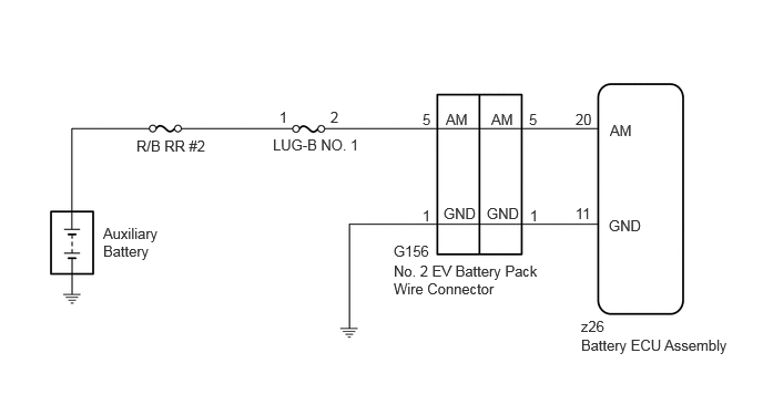
CAUTION / NOTICE / HINT
- CAUTION:
- ·
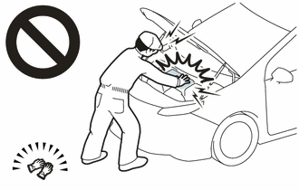
Before the following operations are conducted, take precautions to prevent electric shock by turning the ignition switch off, wearing insulated gloves, and removing the EV battery service plug grip and FC converter power outlet cable on FC converter side.
Make sure to remove the service plug grip first.
-Inspecting the high-voltage system
-Disconnecting the low voltage connector of the inverter with converter assembly
-Disconnecting the low voltage connector of the EV supply battery assembly
-Disconnecting the low voltage connector of the FC converter assembly
-Disconnecting the low voltage connector of the voltage inverter (for 1500W Type Voltage Inverter)
·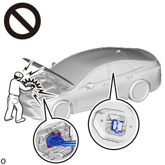
To prevent electric shock, make sure to remove the EV battery service plug grip and FC converter power outlet cable on FC converter side to cut off the high voltage circuit before servicing the vehicle.
·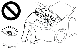
After removing the EV battery service plug grip and FC converter power outlet cable on FC converter side, store them according to the following guidelines to prevent other technicians from accidentally reconnecting them while work is being performed on the high voltage systems.
-The technician performing the work should put the EV battery service plug grip in their pocket and carry it with them.
-Remove the FC converter power outlet cable on FC converter side with a "HIGH-VOLTAGE, DO NOT TOUCH" caution tag attached to it for other technicians.
·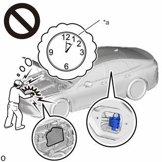 1.667,0.74 2.115,0.427 true 2.188,0.385 2.448,0.552 0.26,0.167 10 false *a
*a Without waiting for 10 minutes
After removing the EV battery service plug grip and FC converter power outlet cable on FC converter side, wait for at least 10 minutes before touching any of the high-voltage connectors or terminals. After waiting for 10 minutes, check the voltage at the terminals in the inspection point in the inverter with converter assembly. The voltage should be 0 V before beginning work.
Click hereEngine / Hybrid System>HYBRID / BATTERY CONTROL>HYBRID BATTERY SYSTEM>PRECAUTION
- HINT:
-
Waiting for at least 10 minutes is required to discharge the high-voltage capacitor inside the inverter with converter assembly and the FC converter assembly.
·Make sure to insulate the high-voltage connectors and terminals of the EV supply battery assembly with insulating tape after removing it.
If the EV supply battery assembly stored without insulating the connectors and terminals, electric shock or fire may result.
- NOTICE:
- ·
After turning the ignition switch off, there may be a waiting time before disconnecting the auxiliary negative (-) battery terminal.
Click hereGeneral>SETUP>WHEN DISCONNECTING OR RECONNECTING BATTERY TERMINAL>BEFORE DISCONNECTING BATTERY
·When disconnecting and reconnecting the auxiliary battery.
Click hereGeneral>SETUP>WHEN DISCONNECTING OR RECONNECTING BATTERY TERMINAL>WORK PROCEDURE
- HINT:
-
When disconnecting and reconnecting the auxiliary battery, there is an automatic learning function that completes learning when the respective system is used.
-
Click hereGeneral>SETUP>WHEN DISCONNECTING OR RECONNECTING BATTERY TERMINAL>AUTOMATIC LEARNING CHART
·This vehicle performs FC system shutdown process after turning the ignition switch off from ON (READY). Therefore, after the ignition switch is turned off from ON (READY), do not perform any work on the electrical system for at least 10 minutes including removing connectors or disconnecting the negative (-) auxiliary battery terminal.
·When the EV control ECU determines that the temperature of FC system components is below 0°C (32°F) when the vehicle is parked with the ignition switch off, it operates the FC air compressor, hydrogen pump and FC cooling water pump for a maximum of 180 seconds to drain the FC stack assembly. When performing inspection or repairs with the ignition switch off (not ON or ON (READY)), disconnect the cable from the negative (-) auxiliary battery terminal before performing work. (If the auxiliary battery voltage is needed to conduct inspection, perform the inspection in an environment with an ambient temperature of 10°C (50°F) or higher.)
PROCEDURE
Pre-procedure1
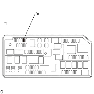
| *1 | Luggage Room Relay Block Assembly |
| *a | LUG-B NO. 1 Fuse |
Remove the LUG-B NO. 1 fuse from the luggage room relay block assembly.
Procedure1
Check if there is an open circuit in the LUG-B NO. 1 fuse in the luggage room relay block assembly.
- OK:
There is no open circuit in the LUG-B NO. 1 fuse.
- Result:
Proceed to OK NG
Post-procedure1
Install the LUG-B NO. 1 fuse.
OK
NG
Pre-procedure1
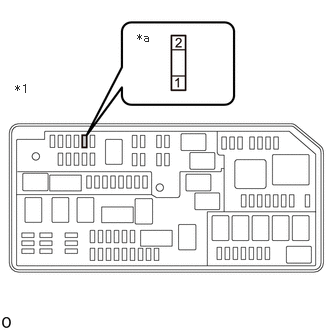
| *1 | Luggage Room Relay Block Assembly |
| *a | LUG-B NO. 1 Fuse Holder |
Remove the LUG-B NO. 1 fuse from the luggage room relay block assembly.
Disconnect the cable from the negative (-) auxiliary battery terminal.
Disconnect the cable from the positive (+) auxiliary battery terminal.
Procedure1
Measure the resistance according to the value(s) in the table below.
- Standard Resistance:
Tester Connection Condition Specified Condition LUG-B NO. 1 fuse holder 1 - Auxiliary battery positive (+) cable Ignition switch off Below 1 Ω LUG-B NO. 1 fuse holder 1 - Body ground Ignition switch off 10 kΩ or higher
- Result:
Proceed to OK NG
Post-procedure1
Connect the cable to the positive (+) auxiliary battery terminal.
Connect the cable to the negative (-) auxiliary battery terminal.
Install the LUG-B NO. 1 fuse to the luggage room relay block assembly.
OK
NG
- CAUTION:
-
Be sure to wear insulated gloves and protective goggles.
Pre-procedure1
Check that the service plug grip and FC converter power outlet cable are not installed.
- NOTICE:
-
After removing the service plug grip and FC converter power outlet cable, do not turn the ignition switch to ON (READY), unless instructed by the repair manual because this may cause a malfunction.
Remove the center No. 2 floor to brace extension.
Procedure1
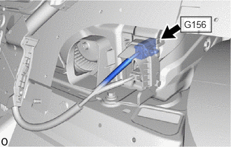
Check the connector connections and contact pressure of the relevant terminals for the G156 No. 2 EV battery pack wire connector.
- HINT:
- OK:
The connectors are connected securely and there are no contact pressure problems.
- Result:
Proceed to OK NG
Post-procedure1
Install the center No. 2 floor to brace extension.
OK
NG
- CAUTION:
-
Be sure to wear insulated gloves and protective goggles.
Pre-procedure1
Check that the service plug grip and FC converter power outlet cable are not installed.
- NOTICE:
-
After removing the service plug grip and FC converter power outlet cable, do not turn the ignition switch to ON (READY), unless instructed by the repair manual because this may cause a malfunction.
Remove the center No. 2 floor to brace extension.
Procedure1
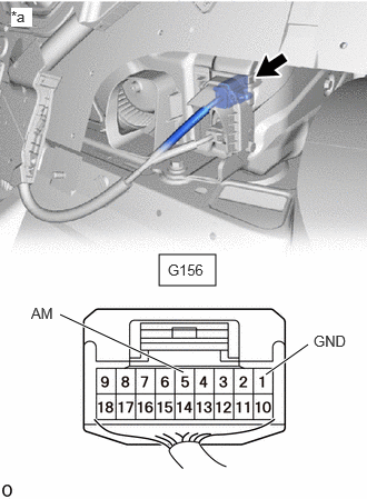
| *a | Component with harness connected
(No. 2 EV Battery Pack Wire Connector) |
Measure the voltage according to the value(s) in the table below.
- Standard Voltage:
Tester Connection Condition Specified Condition Click Location & Routing(G156)Location & Routingewd_type=routing;type=c;code=G156
Click Connector(G156)Body>Floor Wire / No. 3 Floor Wire>EV Supply Battery Assemblyewd_type=component;type=c;code=G156;pinno=5,1
G156-5 (AM) - G156-1 (GND) Ignition switch off 11 to 14 V
- Result:
Proceed to OK NG
Post-procedure1
Install the center No. 2 floor to brace extension.
OK
NG
- CAUTION:
-
Be sure to wear insulated gloves and protective goggles.
Pre-procedure1
Check that the service plug grip and FC converter power outlet cable are not installed.
- NOTICE:
-
After removing the service plug grip and FC converter power outlet cable, do not turn the ignition switch to ON (READY), unless instructed by the repair manual because this may cause a malfunction.
Remove the upper No. 1 EV battery cover sub-assembly.
Procedure1
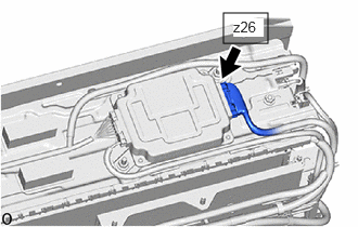
Check the connector connections and contact pressure of the relevant terminals for the z26 battery ECU assembly connector.
- HINT:
- OK:
The connectors are connected securely and there are no contact pressure problems.
- Result:
Proceed to OK NG
Post-procedure1
Install the upper No. 1 EV battery cover sub-assembly.
OK
NG
- CAUTION:
-
Be sure to wear insulated gloves and protective goggles.
Pre-procedure1
Check that the service plug grip and FC converter power outlet cable are not installed.
- NOTICE:
-
After removing the service plug grip and FC converter power outlet cable, do not turn the ignition switch to ON (READY), unless instructed by the repair manual because this may cause a malfunction.
Remove the upper No. 1 EV battery cover sub-assembly.
Disconnect the z26 battery ECU assembly connector.
- NOTICE:
-
Before disconnecting the connector, check that it is not loose or disconnected.
Procedure1
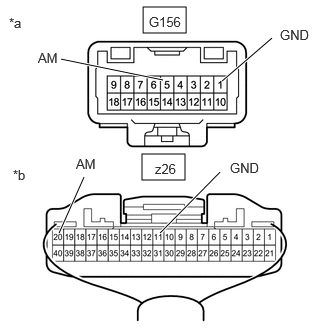
| *a | Front view of wire harness connector
(No. 2 EV Battery Pack Wire Connector) |
| *b | Rear view of wire harness connector
(to Battery ECU Assembly) |
Measure the resistance according to the value(s) in the table below.
- Standard Resistance:
Tester Connection Condition Specified Condition Click Location & Routing(z26,G156)Location & Routingewd_type=routing;type=c,c;code=z26,G156
Click Connector(z26)Body>other>EV Supply Battery Assembly , Battery ECU Assemblyewd_type=component;type=c;code=z26;pinno=20,11
Click Connector(G156)Body>Floor Wire / No. 3 Floor Wire>EV Supply Battery Assemblyewd_type=component;type=c;code=G156;pinno=5,1
z26-20 (AM) - G156-5 (AM) Always Below 1 Ω z26-11 (GND) - G156-1 (GND) Always Below 1 Ω z26-20 (AM) or G156-5 (AM) - Body ground and other terminals Always 10 kΩ or higher z26-11 (GND) or G156-1 (GND) - Body ground and other terminals Always 10 kΩ or higher
- Result:
Proceed to OK NG
Post-procedure1
Reconnect the z26 battery ECU assembly connector.
Install the upper No. 1 EV battery cover sub-assembly.
OK
NG