STEERING COLUMN STEERING COLUMN ASSEMBLY(for Power Tilt and Power Telescopic Steering Column) REMOVAL
CAUTION / NOTICE / HINT
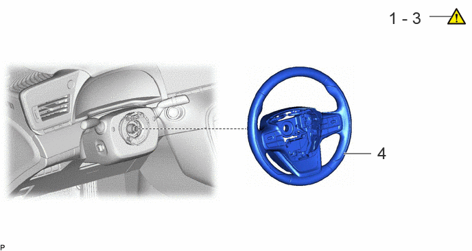
| Procedure | Part Name Code | 
|

|

|
|
|---|---|---|---|---|---|
| 1 | PRECAUTION | - | ( ) |
- | - |
| 2 | CUSTOMIZE POWER TILT AND POWER TELESCOPIC STEERING COLUMN SYSTEM | - | ()
|
- | - |
| 3 | ALIGN FRONT WHEELS FACING STRAIGHT AHEAD | - | - | - | - |
| 4 | STEERING WHEEL ASSEMBLY | 45100 | - | - | - |
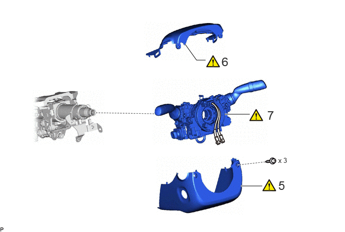
| Procedure | Part Name Code |
|
|
|
|
|---|---|---|---|---|---|
| 5 | LOWER STEERING COLUMN COVER | 45287 | ()
|
- | - |
| 6 | UPPER STEERING COLUMN COVER | 45286B | ()
|
- | - |
| 7 | TURN SIGNAL SWITCH ASSEMBLY WITH SPIRAL CABLE SUB-ASSEMBLY | - | ()
|
- | - |
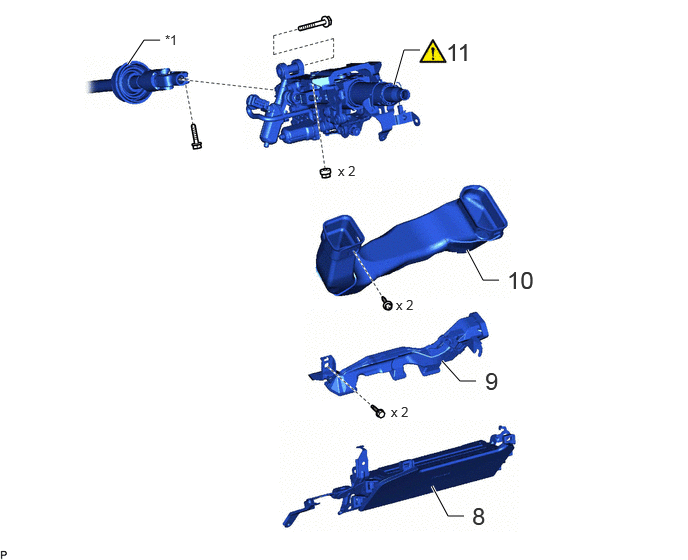
| Procedure | Part Name Code |
|
|
|
|
|---|---|---|---|---|---|
| 8 | LOWER NO. 1 INSTRUMENT PANEL AIRBAG ASSEMBLY | 73900 | - | - | - |
| 9 | AIR DUCT SUB-ASSEMBLY | - | - | - | - |
| 10 | NO. 2 HEATER TO REGISTER DUCT | 55844 | - | - | - |
| 11 | STEERING COLUMN ASSEMBLY | 45250 | ()
|
- | - |
| *1 | NO. 2 STEERING INTERMEDIATE SHAFT ASSEMBLY | - | - |
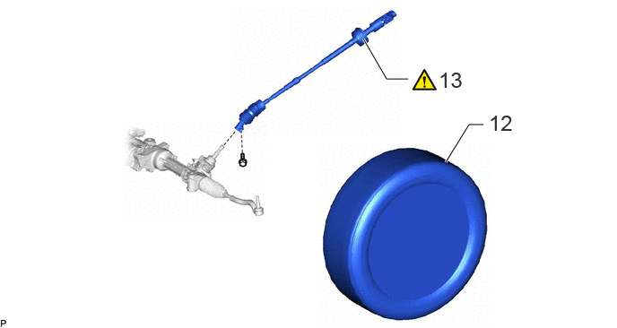
| Procedure | Part Name Code |
|
|
|
|
|---|---|---|---|---|---|
| 12 | FRONT WHEEL LH | - | - | - | - |
| 13 | NO. 2 STEERING INTERMEDIATE SHAFT ASSEMBLY | 45260 | ()
|
- | - |
CAUTION / NOTICE / HINT
The necessary procedures (adjustment, calibration, initialization, or registration) that must be performed after parts are removed and installed, or replaced during steering column assembly removal/installation are shown below.
| Replaced Part or Performed Procedure | Necessary Procedure | Effect/Inoperative Function when Necessary Procedure not Performed | Link |
|---|---|---|---|
| Steering sensor (Including removal and installation) | Steering angle neutral point | Parking assist monitor system | ()
|
| Panoramic view monitor system | ()
|
||
| Steering lock ECU (steering lock actuator or upper bracket assembly) | Code registration (Immobiliser system) | ·
Wireless function ·
Smart function ·
Does not change to on (READY) |
See Service Bulletin for the registration method. |
| Disconnect cable from negative auxiliary battery terminal | Memorize steering angle neutral point | Parking assist monitor system | ()
|
| Panoramic view monitor system | ()
|
- HINT:
-
When the cable is disconnected/reconnected to the auxiliary battery terminal, systems temporarily stop operating. However, each system has a function that completes learning the first time the system is used.
- ·
Learning completes when vehicle is driven
Effect/Inoperative Function When Necessary Procedures are not Performed Necessary Procedures Link Lane tracing assist system Drive the vehicle straight ahead at 35 km/h (22 mph) or more for 5 seconds or more. ( )
Pre-collision system Adaptive high beam system
·Learning completes when vehicle is operated normally
Effect/Inoperative Function When Necessary Procedures are not Performed Necessary Procedures Link Air conditioning system After the ignition switch is turned to ON, theservo motor and expansion valve standardposition is recognized. -
·Use the same procedure for RHD and LHD vehicles.
·The procedure listed below is for LHD vehicles.
PROCEDURE

 1. PRECAUTION
|
|
Click here()
|
2. CUSTOMIZE POWER TILT AND POWER TELESCOPIC STEERING COLUMN SYSTEM
|
|
|
Perform the customization settings.
Click hereSteering>STEERING COLUMN>POWER TILT AND POWER TELESCOPIC STEERING COLUMN SYSTEM>CUSTOMIZE PARAMETERS
Move the steering wheel to its lowest and rearmost position.
3. ALIGN FRONT WHEELS FACING STRAIGHT AHEAD
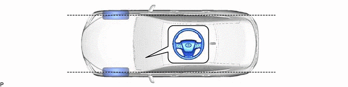
45100
4.REMOVE STEERING WHEEL ASSEMBLY
45287
5.REMOVE LOWER STEERING COLUMN COVER
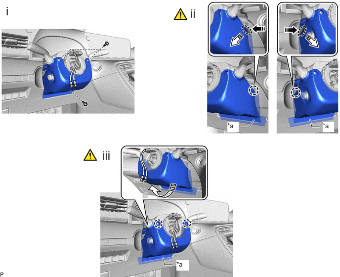
| *a | Felt | - | - |

|
Push Area | 
|
Remove in this Direction (1) |

|
Remove in this Direction (2) | 
|
Remove in this Direction (3) |
Remove the 3 screws.
Press the part in the direction of the arrow shown in the illustration to detach the claw.
- NOTICE:
-
Do not damage the felt.
Detach the 2 claws and remove the lower steering column cover in the direction of the arrow shown in the illustration.
- NOTICE:
-
Do not damage the tilt and telescopic switch and felt.
45286B
6.REMOVE UPPER STEERING COLUMN COVER
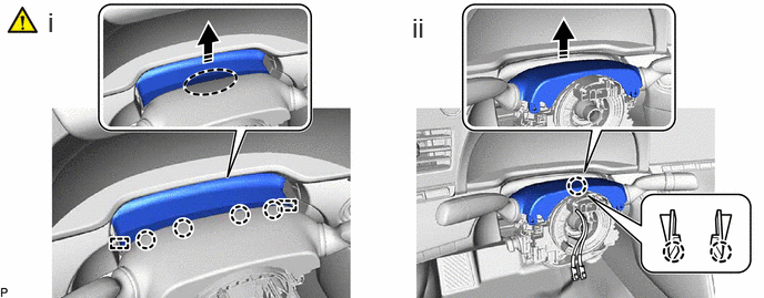
Detach the claws and guides as shown in the illustration.
Disengage the claw to remove the upper steering column cover.
7.REMOVE TURN SIGNAL SWITCH ASSEMBLY WITH SPIRAL CABLE SUB-ASSEMBLY
|
|
|
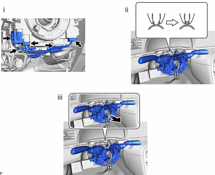
| *a | Clamp | - | - |
|
|
Remove in this Direction | - | - |
Disconnect each connector from the turn signal switch assembly with spiral cable sub-assembly.
Using pliers, support the band clamp while loosened.
Disengage the claw to remove the turn signal switch assembly with spiral cable sub-assembly from the steering column assembly.
73900
8.REMOVE LOWER NO. 1 INSTRUMENT PANEL AIRBAG ASSEMBLY
9.REMOVE AIR DUCT SUB-ASSEMBLY

|
|
Remove in this Direction | - | - |
55844
10.REMOVE NO. 2 HEATER TO REGISTER DUCT

45250
11.REMOVE STEERING COLUMN ASSEMBLY
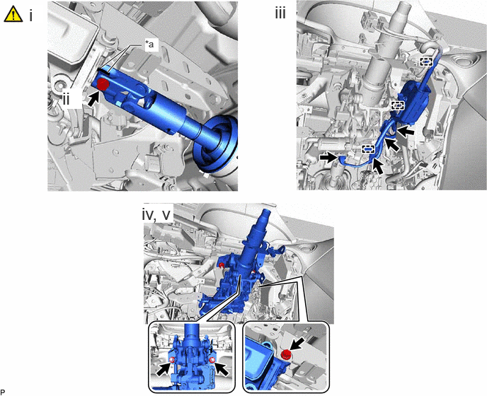
| *a | Matchmark | - | - |
Put matchmarks on the No. 2 steering intermediate shaft assembly and steering column assembly.
Remove the bolt.
Disconnect each connector and disengage each wire harness clamp from the steering column assembly.
Remove the 2 nuts, bolt and steering column assembly.
Disconnect the steering column assembly from the No. 2 steering intermediate shaft assembly.
12.REMOVE FRONT WHEEL LH
45260
13.REMOVE NO. 2 STEERING INTERMEDIATE SHAFT ASSEMBLY
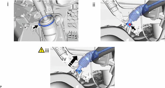
| *a | Matchmark | - | - |
|
|
Slide in this Direction | - | - |
Loosen the clamp.
Remove the bolt.
Slide the No. 2 steering intermediate shaft assembly and put matchmarks on the No. 2 steering intermediate shaft assembly and rack and pinion power steering gear assembly.
Remove the No. 2 steering intermediate shaft assembly from the vehicle.