Home › BRAKE › BRAKE CONTROL › ELECTRONICALLY CONTROLLED BRAKE SYSTEM

DTC    C0210/33    Rear Speed Sensor RH Circuit

DTC    C0215/34    Rear Speed Sensor LH Circuit

DTC    C1273/73    Low Output Signal of Rear Speed Sensor RH (Test Mode DTC)

DTC    C1274/74    Low Output Signal of Rear Speed Sensor LH (Test Mode DTC)

for Preparation Click here


DESCRIPTION

Refer to DTC C0200/31 and C0205/32 .
DTCs C1273/73 and C1274/74 can be deleted when the speed sensor sends a vehicle speed signal or the Test Mode ends. DTCs C1273/73 and C1274/74 are output only in the Test Mode.

DTC No.
INF Code
DTC Detection Condition
Trouble Area
C0210/33
277
278
279
280
281
282
283
284
285
286
287
288
When one of following conditions is met:
  1. Speed of a malfunctioning wheel is 0 mph (0 km/h) for at least 15 sec. when vehicle speed is 6 mph (10 km/h) or more.
  2. Speed of the slowest wheel is less than 1/7th of the 2nd slowest wheel for at least 15 sec. when vehicle speed is 6 mph (10 km/h) or more.
  3. Abnormal high wheel speed pulse is input for at least 15 sec.
  4. Abnormal high wheel speed pulse is input at least 7 times when ECU is on.
  5. Speed sensor pulse signal is instantly cut 7 times or more.
  6. Speed sensor signal line is open for at least 0.5 sec.
  1. Right rear and left rear speed sensor
  2. Each speed sensor circuit
  3. Sensor rotor
  4. Sensor installation
  5. Skid control ECU
C0215/34
290
291
292
293
294
295
296
297
298
299
300
301
When one of following conditions is met:
  1. Speed of a malfunctioning wheel is 0 mph (0 km/h) for at least 15 sec. when vehicle speed is 6 mph (10 km/h) or more.
  2. Speed of the slowest wheel is less than 1/7th of the 2nd slowest wheel for at least 15 sec. when vehicle speed is 6 mph (10 km/h) or more.
  3. Abnormal high wheel speed pulse is input for at least 15 sec.
  4. Abnormal high wheel speed pulse is input at least 7 times when ECU is on.
  5. Speed sensor pulse signal is instantly cut 7 times or more.
  6. Speed sensor signal line is open for at least 0.5 sec.
  1. Right rear and left rear speed sensor
  2. Each speed sensor circuit
  3. Sensor rotor
  4. Sensor installation
  5. Skid control ECU
C1273/73
C1274/74
-
Detected only during Test Mode
  1. Rear speed sensor
  2. Rear speed sensor circuit
  3. Sensor rotor
  4. Sensor installation

HINT:
  1. DTC C0210/33 is for the right rear speed sensor.
  2. DTC C0215/34 is for the left rear speed sensor.
  3. The BRAKE warning light comes on when speed sensor malfunctions are detected in two or more wheels.


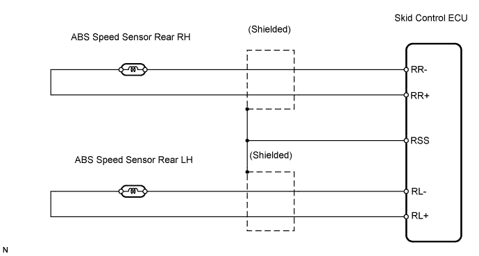
WIRING DIAGRAM


C126244E03


INSPECTION PROCEDURE

NOTICE:
When replacing the skid control ECU, perform initialization of linear solenoid valve and calibration (Click here).

1.CHECK HARNESS AND CONNECTOR (MOMENTARY INTERRUPTION)
  1. Using Techstream, check for any momentary interruption in the wire harness and connector corresponding to a DTC (Click here).

    ABS / VSC / TRAC: 
    Tester Display
    Measurement Item/Range
    Normal Condition
    Diagnostic Note
    RR Speed Open
    RR speed sensor open detection / OPN-DET or NORMAL
    NORMAL: Normal condition
    -
    RL Speed Open
    RL speed sensor open detection / OPN-DET or NORMAL
    NORMAL: Normal condition
    -

    OK:
    There are no momentary interruption.

    HINT:
    Perform the above inspection before removing the sensor and connector.


NG
Go to step 5
OK


2.READ VALUE OF TECHSTREAM (REAR SPEED SENSOR)
  1. Check the Data List for proper functioning of the rear speed sensor.

    ABS / VSC / TRAC: 
    Tester Display
    Measurement Item/Range
    Normal Condition
    Diagnostic Note
    RR Wheel Speed
    Wheel speed sensor (RR) reading / min.: 0 km/h (0 mph), max.: 326 km/h (202 mph)
    Actual wheel speed
    Similar speed as indicated on speedometer
    RL Wheel Speed
    Wheel speed sensor (RL) reading / min.: 0 km/h (0 mph), max.: 326 km/h (202 mph)
    Actual wheel speed
    Similar speed as indicated on speedometer

    OK:
    There is almost no difference in the displayed speed value.

    HINT:
    There is tolerance of +-10% in the speedometer indication.


NG
Go to step 4
OK


3.INSPECT SPEED SENSOR AND SENSOR ROTOR SERRATIONS


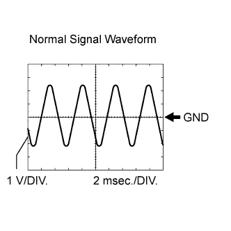
    F100551E10
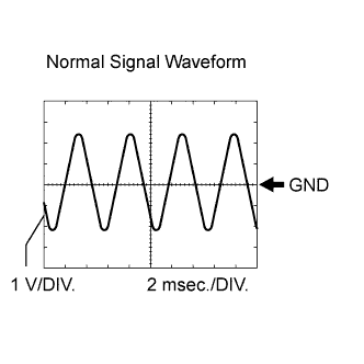
  1. Connect the oscilloscope to terminals RR+ and RR-, or RL+ and RL- of the skid control ECU.

  1. Drive the vehicle at approximately 30 km/h (19 mph), and check the signal waveform.

    OK:
    A waveform as shown should be output.

    HINT:
    1. As the vehicle speed (wheel revolution speed) increases, a cycle of the waveform narrows and the fluctuation in the output voltage becomes greater.
    2. When noise is identified in the waveform on the oscilloscope, error signals are generated due to the speed sensor rotor's scratches, looseness or foreign matter deposited on it.


NG
Go to step 7
OK

REPLACE SKID CONTROL ECU 

4.INSPECT REAR SPEED SENSOR


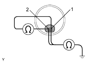
    F041836E21
  1. Disconnect the rear speed sensor connector.

  1. Measure the resistance of the sensor.

    Standard resistance:
    Tester Connection
    Specified Condition
    1 - 2
    1.04 to 1.30 kΩ
    1 - Body ground
    10 kΩ or higher
    2 - Body ground
    10 kΩ or higher

NOTICE:
Check the speed sensor signal after the replacement (Click here).


NG
REPLACE REAR SPEED SENSOR
OK


5.CHECK WIRE HARNESS (SKID CONTROL ECU - REAR SPEED SENSOR)


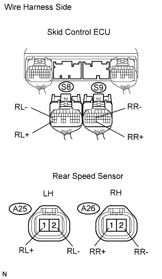
    C126272E01
  1. Disconnect the S8 and S9 ECU connectors.

  1. Disconnect the A25 and A26 sensor connectors.

  1. Measure the resistance of the wire harness side connectors.

    Standard resistance:
    for LH:
    Tester Connection
    Specified Condition
    A25-1 (RL+) - S8-35 (RL+)
    Below 1 Ω
    A25-2 (RL-) - S8-27 (RL-)
    Below 1 Ω
    A25-1 (RL+) - Body ground
    10 kΩ or higher
    A25-2 (RL-) - Body ground
    10 kΩ or higher
    for RH:
    Tester Connection
    Specified Condition
    A26-1 (RR+) - S9-31 (RR+)
    Below 1 Ω
    A26-2 (RR-) - S9-23 (RR-)
    Below 1 Ω
    A26-1 (RR+) - Body ground
    10 kΩ or higher
    A26-2 (RR-) - Body ground
    10 kΩ or higher


NG
REPAIR OR REPLACE HARNESS AND CONNECTOR
OK


6.INSPECT SPEED SENSOR AND SENSOR ROTOR SERRATIONS


    F100551E11
  1. Connect the oscilloscope to terminals RR+ and RR-, or RL+ and RL- of the skid control ECU.

  1. Drive the vehicle at approximately 30 km/h (19 mph), and check the signal waveform.

    OK:
    A waveform as shown should be output.

    HINT:
    1. As vehicle speed (wheel revolution speed) increases, a cycle of the waveform narrows and the fluctuation in the output voltage becomes greater.
    2. When noise is identified in the waveform on the oscilloscope, error signals are generated due to the speed sensor rotor's scratches, looseness or foreign matter deposited on it.


NG
Go to step 7
OK

REPLACE SKID CONTROL ECU 

7.REPLACE SKID CONTROL ECU


    F010178E20
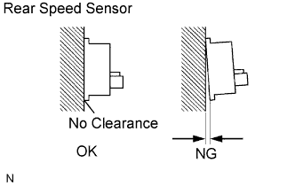
  1. Check the sensor installation.

    OK:
    There is no clearance between the sensor and rear axle carrier.

    NOTICE:
    Check the speed sensor signal after the replacement (Click here).


NG
REPLACE REAR SPEED SENSOR
OK

REPLACE SKID CONTROL ECU